16-bit high definition oscilloscopes for accurate measurements in electric and hybrid cars

The power efficiency of the drive electronics is a key parameter when developing electric drive systems. The conduction loss of the electric drive electronics is of special interest. One important parameter for determining the conduction loss is the RDS(on) of the MOSFET. When a switching MOSFET is off, it has a high drain-to-source voltage, but when it is turned on, the voltage drops to just a few hundred millivolts. A highresolution oscilloscope is needed to measure these low voltages. Probe compensation and correct probing are also vital for accurate RDS(on) measurements.

measuring-rds-high-definition-oscilloscopes_ac_3607-1320_92_01.png

Your task

To calculate the RDS(on) of a MOSFET operating in inverse mode, the drain current and the drain-to-source voltage need to be measured. However, due to the high drain-to-source voltage in the off state and peaks during switching, it is difficult to measure the relatively small drain-to-source voltage in the on state with the typical 8-bit resolution of standard oscilloscopes. In addition, poor probe compensation and incorrect probing techniques can significantly distort the signal, resulting in incorrect measurement results even when the oscilloscope offers the necessary dynamic range.

T&M Solution

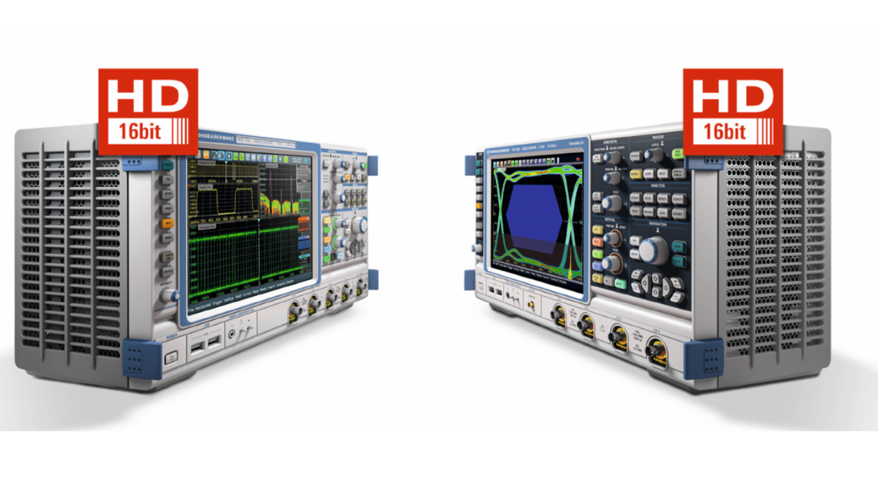
With the R&S®RTO/R&S®RTE oscilloscope, the R&S®RTO/R&S®RTE high definition mode and the right probing techniques, it is possible to measure the drain-to-source voltage for RDS(on) under high dynamic range conditions. Thanks to digital lowpass filtering, a vertical resolution of up to 16 bit is achieved, reducing the noise and increasing the signal-to-noise ratio.

The user can limit the bandwidth (selectable bands) from 1 GHz to 10 kHz (10 bit to 16 bit). This makes it possible to see small signal details such as the drain-to-source voltage in switching power supply applications that would otherwise vanish in noise.

Application

The right probing techniques and probing compensation for accurate measurements

When measuring signals with high frequency components, a key aspect in probing is to keep the “loop” formed by the probing connections (signal pin and ground connection) as short as possible. The spring-loaded tip of the R&S®RT-ZP10 passive probe together with the ground contact springs provides a safe contact with minimal noise and interference coupling on the measured signal. It is therefore possible to directly probe the MOSFET pins and body. Accurate probe compensation is also very important for high-resolution measurements. A poorly compensated probe introduces measurement errors, resulting in an inaccurate reading. This can also influence the differential measurements suggested in this application card.

For measurements where none of the MOSFET pins are grounded, an active differential probe has to be used. The R&S®RT-ZD10 1 GHz active differential probe is particularly useful here as it comes with an additional 10:1 attenuator that extends the probe’s voltage range to 70 V DC / 46 V AC (peak).

Analyzing very small signal details in the high definition mode

The R&S®RTO-K17/R&S®RTE-K17 high definition option offers users a very flexible way of increasing the resolution of an R&S®RTO/R&S®RTE digital oscilloscope. The software option uses digital filtering to increase the oscilloscope resolution. A maximum resolution of 16 bit is possible, enabling detailed analysis even under extremely high dynamic range conditions. The high definition mode can be quickly set up in just a few steps:

  • Press the “Mode” button.
  • On the “Acquisition” tab, press “Option Mode” and select “High definition”.
  • Adjust the bandwidth as needed. The resulting resolution is displayed automatically.

The selected bandwidth should be as low as needed in order to obtain sufficient resolution but as high as possible to minimize signal distortion due to filtering. The ideal measurement bandwidth has to be determined case by case.

Avoiding offset problems when calculating RDS(on)

Measuring at such different voltage levels requires additional steps to get the correct result. The offset accuracy of oscilloscopes no longer suffices to simply divide the drain-to-source voltage across the MOSFET by the drain current to calculate RDS(on). And when Rogowski probes are used to measure the current through the drain pin of the MOSFET, only the AC component of the drain current can be measured. The resulting current measurement on the oscilloscope will therefore have a DC offset.

This problem is solved by taking advantage of the fact that the drain current exhibits a constant or almost constant slope for a certain time interval while the MOSFET is in the on state. It therefore makes sense to use a differential method to calculate RDS(on) in high definition mode:

  • Adjust the vertical scale of the oscilloscope such that the maximum drain-to-source voltage including peaks does not exceed the input voltage range of the oscilloscope. Otherwise, overload and saturation effects will decrease the accuracy of the drain-to-source voltage measurement.
  • Use the zoom mode to display the drain-to-source voltage so that the slope of the drain-to-source voltage is clearly visible.
  • Enable averaging of waveforms to get rid of any remaining unwanted noise or interference.
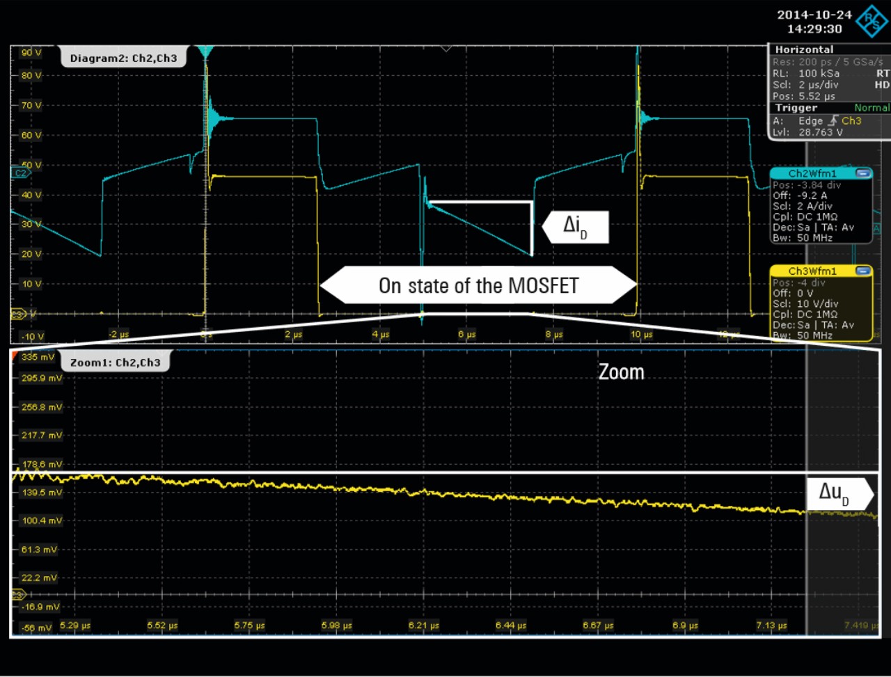
  • Measure the slope of the drain-to-source voltage to get ΔuD.
  • Measure the slope of the drain current of the MOSFET in the same time interval as ΔuD to get ΔiD.
  • Calculate RDS(on) by dividing ΔuD by ΔiD.

The screenshot illustrates the measurement.

Using waveform averaging in high definition mode with 50 MHz bandwidth, which increases the vertical resolution to 16 bit, the greatly magnified waveforms are very clearly displayed.

Summary

The R&S®RTO-K17/R&S®RTE-K17 high definition option makes it possible to measure signal details that would be lost in the noise of typical 8-bit oscilloscopes. It is possible to measure parameters like RDS(on) in switched-mode power supply applications where the measured signal exhibits a high dynamic range. Care has to be taken to use the right probing techniques and accurate probe compensation as both can introduce significant errors in the measurement result. It is recommended to verify the result of such high dynamic measurements by performing the measurement under various conditions to make sure that the measurement is accurate.

Related solutions