Advanced trigger based multichannel pulse analysis to characterize radar warning receivers

Phase difference is the key parameter when characterizing direction finding (DF) scenarios. To analyze DF equipment, the phase difference needs to be determined before measuring other parameters such as the bearing. The R&S®VSE-K6A multichannel pulse analysis software in combination with a Rohde & Schwarz oscilloscope provides phase difference measurements even in challenging environments, utilizing the test equipment’s advanced trigger capabilities.

Radar warning receiver
Open Lightbox

Your task

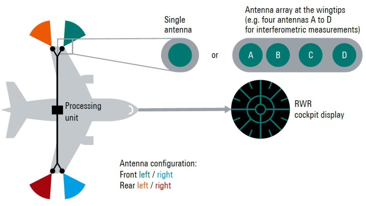
A radar warning receiver (RWR, see figure above) usually consists of multiple receivers which are evaluated together to determine the direction of an incoming radar pulse. Usually, the more receivers are combined, the better is the angular accuracy of the bearing.

The direction finding (DF) method used may depend on the application in question; typical methods are time difference of arrival (TDOA) and correlative interferometer. In any case, R&D measurements require a phase coherent receiver to measure the phase difference between the receivers. At the development stage, receiver performance is measured under ideal conditions and frequently also in more demanding scenarios.

Rohde & Schwarz solution

The R&S®RTO and R&S®RTP oscilloscopes are time-domain instruments, and their input channels are designed for time-coherent signal acquisition.

A potential skew (difference in propagation delay) resulting from the measurement setup may be adjusted 1). Advanced trigger capabilities are available to isolate events and analyze them in greater detail. The following shall illustrate a challenging scenario and demonstrate the capabilities of an oscilloscope as a powerful debugging tool.

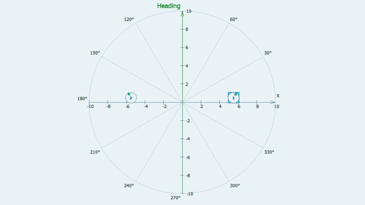
Fig. 1: Spatial configuration of the RWR. The receivers are slightly tilted toward port and starboard.
Open Lightbox

Measurement setup

The setup includes the R&S®Pulse Sequencer software to simulate a scenario in the X band (8 GHz to 12 GHz), and a dual-channel R&S®SMW200A vector signal generator to provide the required signals. The R&S®RTP oscilloscope in combination with the R&S®VSE vector signal explorer software takes care of analysis. To demonstrate a phase difference, only two antennas of an RWR are simulated. They are placed 11 m apart from starboard to port at the wingtips of an airplane. In addition, to ease the simulation effort, every object is placed at the same height, leaving only two degrees of freedom available (e.g. east and north coordinates).

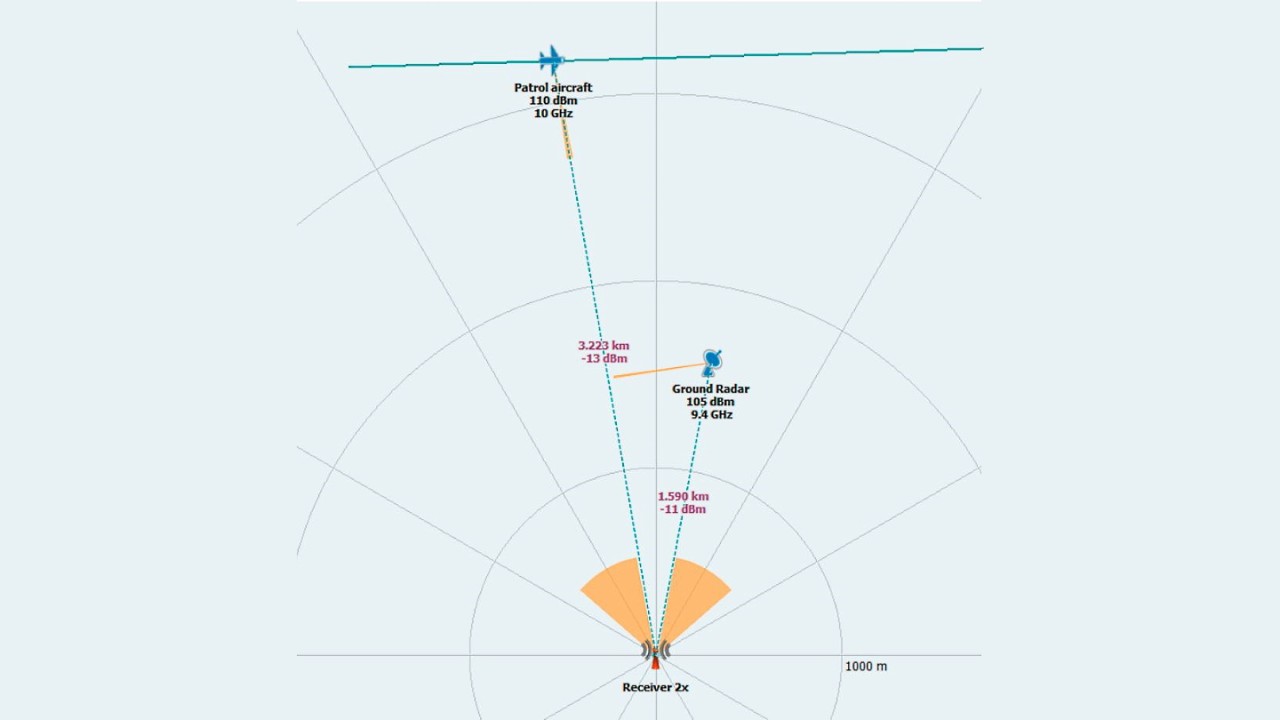
Often, a situation is not static but instead the RWR must cope with dynamic scenarios. The scenario in this example consists of a moving emitter (generating varying amplitudes) and a stationary emitter. The RWR is kept stationary. Figs. 1 and 2 show the spatial configuration generated by the R&S®Pulse Sequencer. An airborne radar (patrol aircraft) operating in the X band tracks the RWR and moves laterally past it.

Fig. 2: Dynamics of the simulated scenario. The airborne radar is directed at the RWR, while the ground radar is set to isotropic emission.
Open Lightbox

There is another radar (ground radar) operating in the X band with a power level at the RWR input similar to that of the airborne radar. The second radar acts as a disturber in RWR analysis.

The pulses from the ground radar have pulse repetition intervals (PRIs) and power levels similar to those of the airborne radar. While the signal from the ground radar is weaker at the port receiver and stronger at the starboard receiver, the power level from the airborne radar is at its maximum at the port receiver, decreases as it moves past the RWR, and returns to its maximum at the starboard receiver.

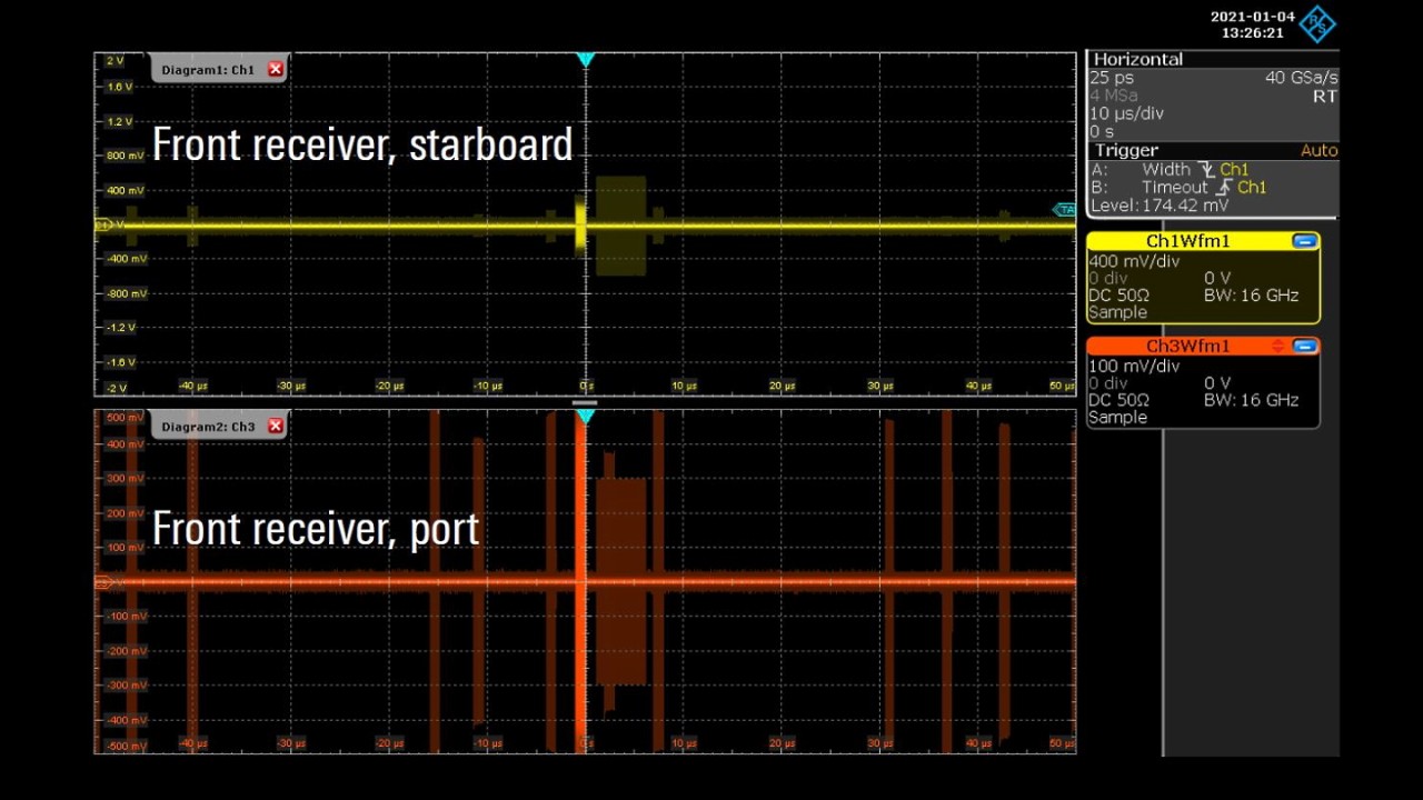
Fig. 3: With only auto trigger in place, a stable trigger condition is not achieved. However, a first overview of the scenario can be established to find proper trigger conditions.
Open Lightbox

Determining the phase difference in a DF scenario is key. An initial simple triggering on the two signals received by the R&S®RTP oscilloscope reveals a rather mixed view (see Fig. 3).

The oscilloscope displays a pulse of 5 μs duration for both receivers and an intermittent 1 μs signal randomly distributed around the 5 μs signal. In fact, these are the predefined values for the scenario simulated with the R&S®Pulse Sequencer software.

Type Pulse duration PRI Modulation
Patrol aircraft 1 μs 100 μs None
Ground radar 5 μs 20 μs Barker 13

As mentioned above, the pulses from the ground radar are frequent and shall not be included in the analysis. The simulated movement of the aircraft spans a range of 3 km, traversed at a speed of 400 m/s, resulting in approximately 7.5 s for a one-way trip. In this timeframe, one can expect approximately 75 000 pulses from the aircraft. Covering 7.5 s in a single acquisition is not a viable option as this would require 2 × 40 Gsample/s × 7.5 s = 600 Gsample of memory. A proper trigger condition to isolate the 1 μs pulses in the time domain is mandatory.

Trigger condition

The trigger condition is explained in detail in the application card “Trigger on radar RF pulses with an oscilloscope” (PD 3609.2000.92). The pulses from the patrol aircraft can be isolated using the described trigger setup:

Trigger A
Trigger A
Open Lightbox
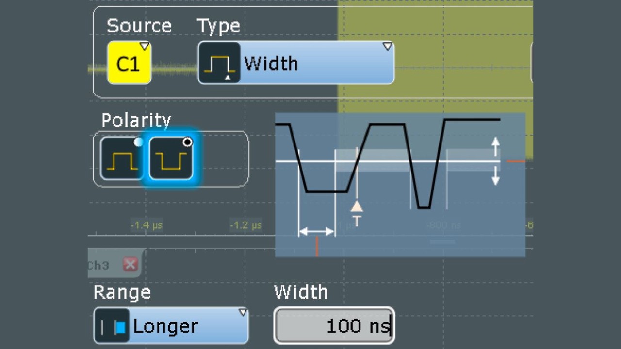
  • Trigger A (width trigger with an off time longer than 100 ns). This provides a stable trigger for every pulse (including pulses not to be considered in the analysis)
Trigger B
Trigger B
Open Lightbox
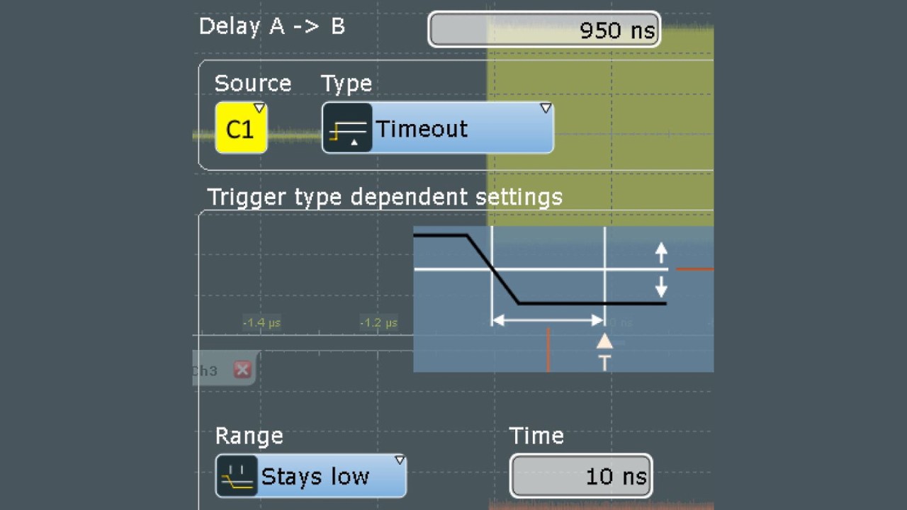
  • Trigger B (timeout trigger). The trigger occurs when a pulse has remained below threshold level for 10 ns. Trigger B is evaluated after a delay a bit smaller than the intended pulse duration, e.g. after 95 % (this condition will still capture all pulses longer than this delay)
Trigger C
Trigger C
Open Lightbox
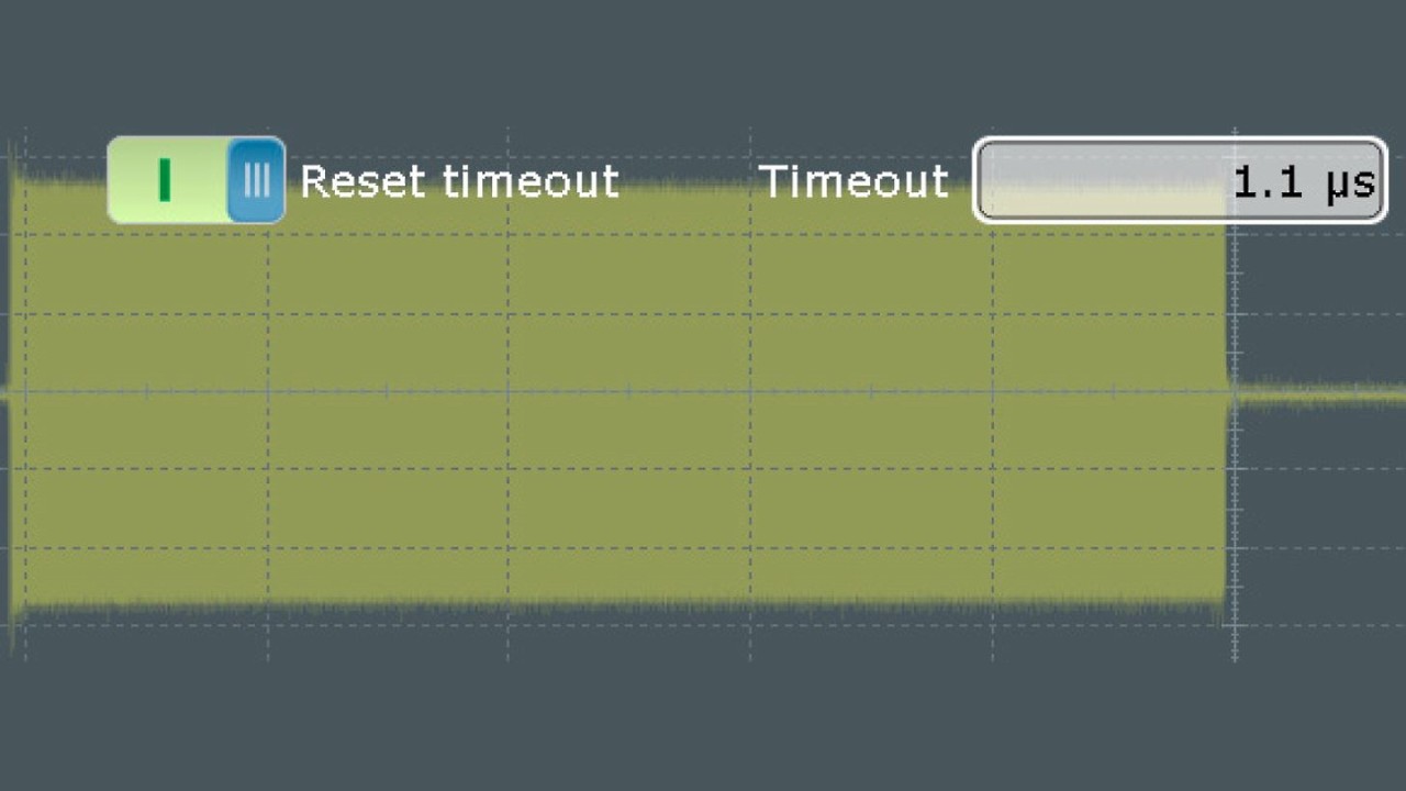
  • Trigger R (reset timeout a little bit higher than the intended pulse duration, e.g. 10 %). This condition rejects every pulse longer than the specified timeout. As a result, only the 1 μs pulses will be considered
Both channels of the R&S®RTP are sampled at a rate of 40 Gsample/s.
Open Lightbox

Analysis settings

Analysis can be performed either directly on the R&S®RTP (see application card “Analyzing RF radar pulses with an oscilloscope” (PD 5215.4781.92) and application note “Automotive Radar – Chirp Analysis with R&S®RTP Oscilloscope” (GFM318)), or using a dedicated analysis software. The R&S®VSE vector signal explorer software with the R&S®VSE-K6A multichannel pulse analysis option quickly determines the phase difference as well as other important radar parameters such as pulse width and droop.

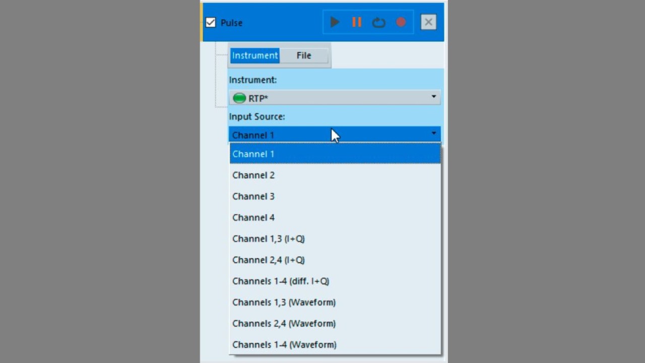
Channels 1 and 3 are chosen as input channels, and waveform mode is selected. As a result, both channels of the R&S®RTP are sampled at a rate of 40 Gsample/s.

Now the oscilloscope is ready for signal acquisition.
Open Lightbox

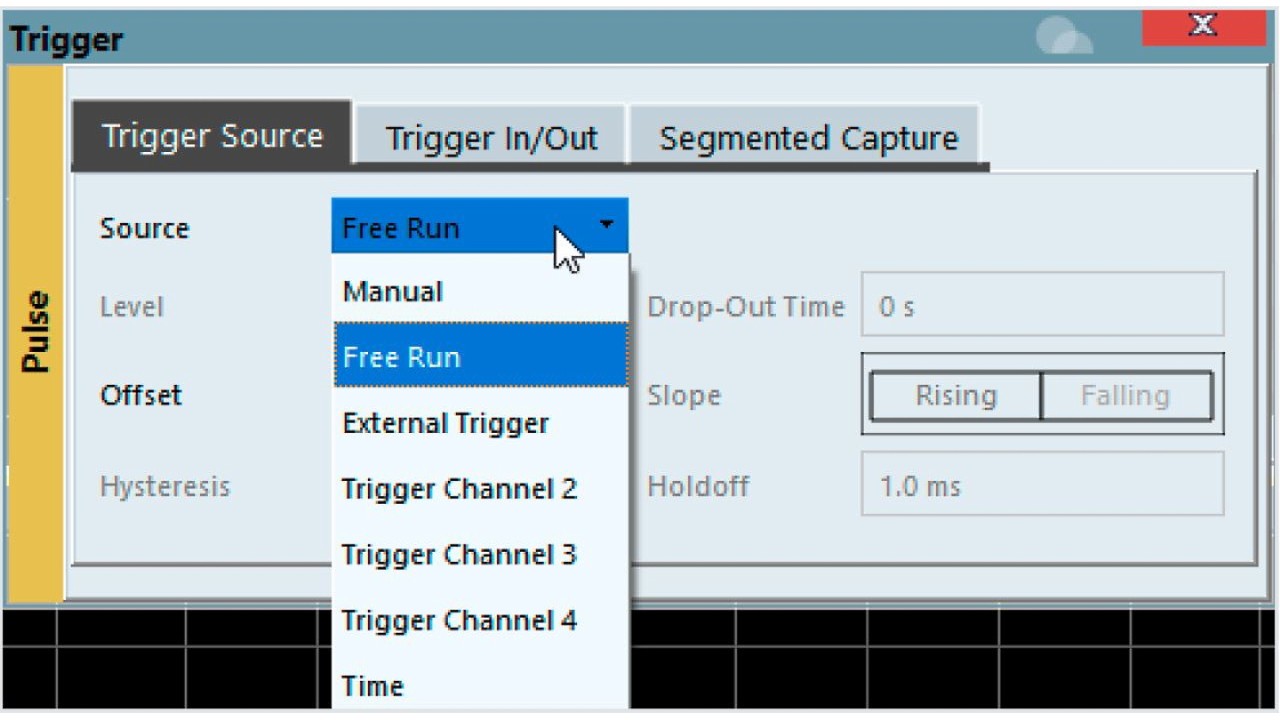
After setting important parameters such as center frequency and acquisition time and configuring the detection algorithm, the R&S®VSE is set to manual trigger mode. The aforementioned trigger settings are applied to the R&S®RTP. In addition, a negative trigger offset can be defined to ensure proper timing since the trigger shifts pulse acquisition to the left of the trigger mark. Now the oscilloscope is ready for signal acquisition.

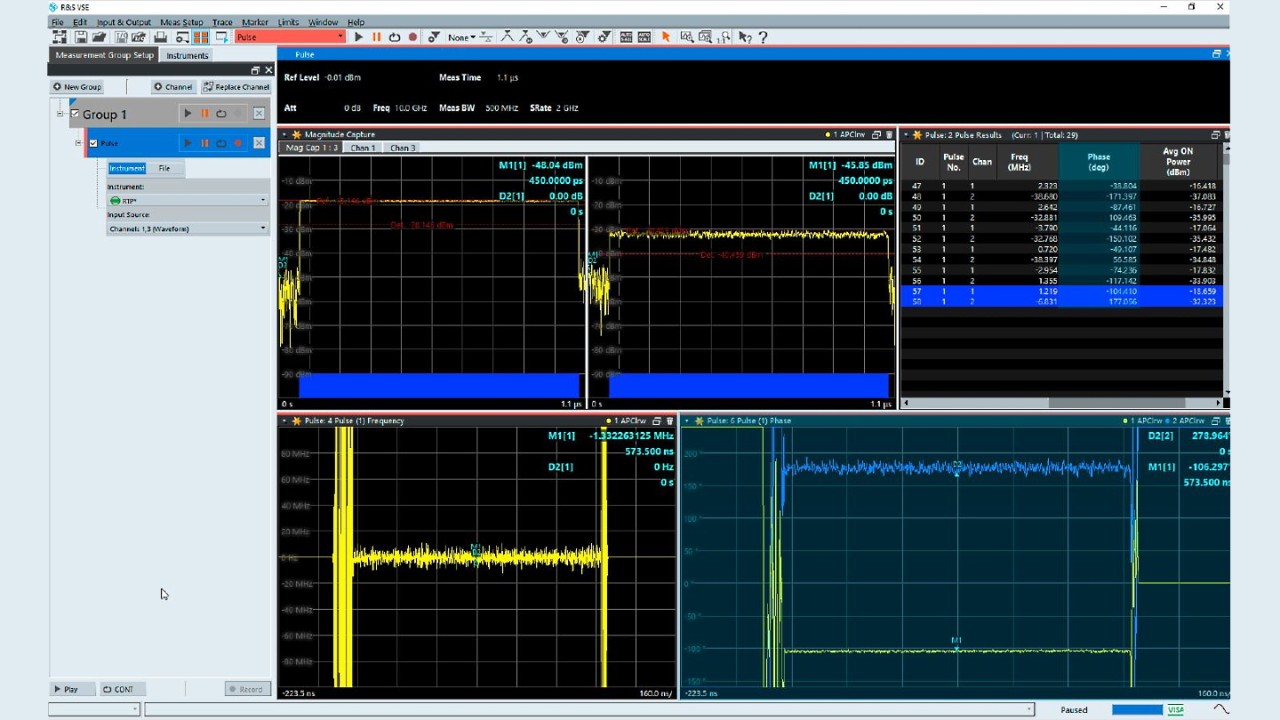
Fig. 4: Main analysis view of the R&S®VSE-K6A multichannel pulse analysis option. The phase difference can be determined either via markers (bottom right window) or from the values in the results table (top right window).
Open Lightbox

Among the main analysis tools in multichannel analysis are the pulse phase (wrapped) and pulse phase (unwrapped) measurement functions (see bottom right window in Fig. 4). A new trace is generated and assigned to channel 3. The phase difference can now be measured by placing markers on the two curves and linking the markers together. The delta marker reveals a phase difference of 279° in this example. The phase difference can also be determined from the values in the results table (top right window).

Summary

Phase difference measurements require phase coherent receivers. In addition, especially in challenging scenarios, a suitable trigger condition can speed up analysis of the radar signal of interest. The R&S®VSE-K6A multichannel pulse analysis option utilizes the complete range of digital trigger functions available on the R&S®RTO and R&S®RTP oscilloscopes. It delivers automatic analysis of the most important radar parameters combined with automatic phase difference measurement.

Related solutions