Written by Jens Berger | October 17, 2022


This study looks at data latency in real-field mobile networks. Recently, we discussed how distance to the server can impact latency and jitter and how changing conditions in mobile networks affect latency.
Now, we will make a distinction between the uplink and downlink directions to study the occurrence of delay jitter in each direction. Packet loss will also be studied in more detail. Again, all analysis is based on measurements obtained in mobile networks while moving.
How the latency was measured
To obtain realistic latency measurements, a typical data stream for real-time applications was emulated by using the two-way active measurement protocol (TWAMP) in line with IETF RFC 5357. It is based on the user datagram protocol (UDP) applied for most real-time network communications. We transported thousands of UDP packets to a network server and back. To receive realistic latencies, we selected packet frequencies and sizes typical for real-time applications.
Packet delay variation
In mobile networks, the uplink transmission is different from the downlink. Typically, the use of the radio transmission differs based on beamforming and radiation. In frequency division duplex (FDD) networks, the uplink uses a different frequency than the downlink. For carrier aggregation such as in 4G and 5G, frequencies used for uplink and downlink can be further away from each other even in the usual case of time division duplexing (TDD).
Moreover, the majority of radio resources are usually assigned to the downlink transmission, since the traffic to the UEs is much higher than in opposite direction. Thus, the transmission and the resulting latency performance can be very different depending on the direction.
A UDP packet stream 10 seconds in length with bit rates between 0.1 Mbit/s and 1 Mbit/s was used for testing traffic patterns and transported over 4G and 5G EN-DC cellular radio technologies. Both measurement campaigns were conducted under difficult mobility conditions (on a train and heavy traffic).
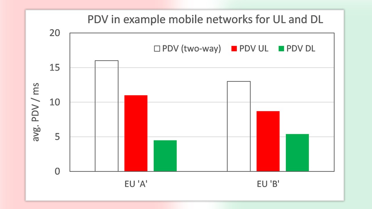
The median two-way latency is around 40 ms, while the two-way packet delay variation (PDV) is about 14 ms for both measurement campaigns. The question was now in which direction more PDV would be added – uplink or downlink.
The following results show that the uplink direction more often causes delay jitter than the downlink. However, these are statistical results over the entire test campaign. Looking at the results in more detail shows that individual root causes such as poor radio conditions and cell changes have a different influence on the two directions.


For both of the example networks, the packet delay variation in the uplink direction (from the mobile client to a reflecting cloud server in the network) is visibly higher than in the downlink. This specific information is highly important for network optimization and to rate the network performance for interactive and real-time services that have different packet jitter demands in the two directions.
These simple average values make it clear that – even with identical bit rate conditions and technologies – the contribution of UL and DL to the PDV is not the same, not even relatively. This demonstrates the influence of network settings and infrastructure.
Here, only average values for a single pattern are presented. A separated analysis for individual load patterns and technologies will provide even more detailed insights. Latency and PDV are of course affected by network load and radio technology, but also by bit rate, packet size and packet frequency.
Packet loss
Most real-time interactive applications cannot wait for heavily delayed packets. The application discards packets that are too late and treats them as lost. The length of this “delay budget” depends on the use case; 3GPP for example defines 50 ms one-way latency for online gaming and 150 ms for video chats.
When studying the influence of latency and packet arrival on perceived interactivity, we should consider heavily delayed packets as unusable for the application and consider them as discarded. At the application level, there is no difference between genuinely lost packets that never arrive and corrupted packets that cannot be used. Both are considered as lost. Nevertheless, from a network evaluation perspective, it is interesting to see how many packets are discarded by a delay exceeding the defined delay budget and how many are lost.
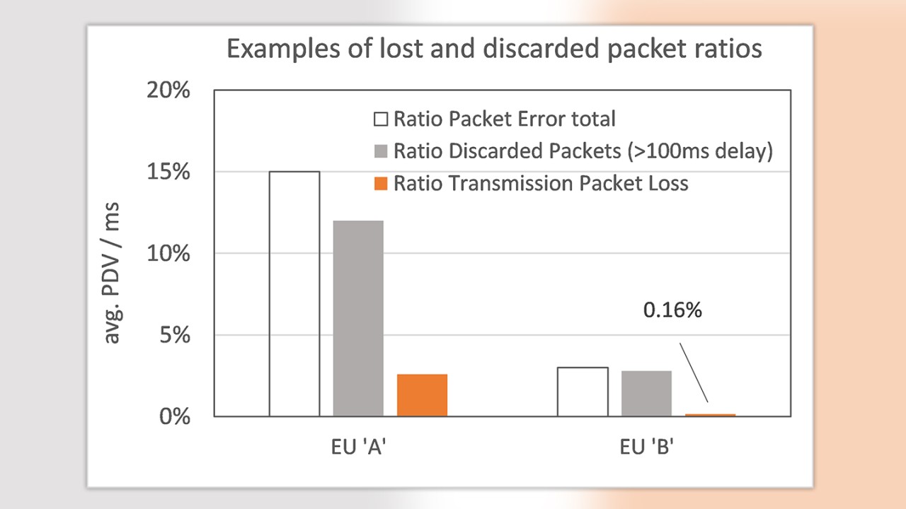
For the data stream in these campaigns, a two-way delay budget of 100 ms was assumed. Packets that were not received or delayed by more than the defined 100 ms were grouped together as “packet errors.” To provide more information, this packet error ratio was separated into lost packets (not received at all) and packets travelling for longer than 100 ms (and considered as discarded) but received later.


The number of packets actually lost during transmission is significantly lower than the total number of packet errors, with the majority of these packets being discarded due to a long delay. This ratio is heavily affected by the delay budget of 100 ms, which is demanding for current public networks. We have observed a round-trip latency median of 40 ms in these examples, with many individual packets exceeding the 100 ms threshold. The results may change once networks offer shorter delays and provide more consistent latencies.
The very high ratio of disqualified and lost packets in the EU ‘A’ network can be attributed to the measurement campaign being conducted on a public train.
Conclusion
We believe that separating results by direction (uplink and downlink) enables network problems to be discovered and improved more efficiently.
The extended analysis, where packet delay variation and even packet loss can be reported separately for either direction, is based on an extended protocol analysis of the TWAMP method. The computation and reporting of these additional results is now fully integrated into the Rohde & Schwarz interactivity test supported by all MNT products.
The interactivity test for measuring packet delay under realistic conditions will be further extended in the near future to provide even more useful information for troubleshooting and optimization. The test procedure is part of a family of test and measurement applications that provide insights into all aspects of packet transport.
Read more about interactivity test in part 1 - 8 of this series and download our white paper "Interactivity test:
Interactivity test: QoS/QoE measurements in 5G (part 1)
Interactivity test: Concept and KPIs (part 2)
Interactivity test: Examples from real 5G networks (part 3)
Interactivity test: Distance to server impact on latency and jitter (part 4)
Interactivity test: Impact of changing network conditions on latency and jitter (part 5)
Interactivity test: Dependency of packet latency on data rate (part7)


