Written by Arnd Sibila | December 29, 2016


The Mulitiple Input Multiple Output (MIMO) method is fundamental in LTE system design. 4x4 MIMO's potential lies in enabling radio systems to achieve significant performance gains by using multiple (4) antennas at their transmitters and receivers. It has already been specified in the 3GPP Release 8, the first LTE standardization release, frozen in 2008. 3GPP's (3rd Generation Partnership Project) latest Release 13 is currently frozen. It is only now that operators are planning 4×4 MIMO deployments.
MIMO can be described as spatial multiplexing. It enables the transmission of more than 1 signal to 1 user via the same set of air interface resources. The feature builds on uncorrelated paths. In other words, it builds on uncorrelated transmit and receive antennas and uncorrelated paths (multipath) on the air interface (the channel).
4×4 MIMO means that with the same resource blocks in the air interface, the base station transmits 4 different signals (or streams) via 4 transmit antennas to one user equipment (UE). To receive the signals and benefit most, however, the UE must be equipped with 4 antennas. In theory, this doubles the downlink throughput per resource block compared with 2×2 MIMO, today's state-of-the-art MIMO operating mode.
To discuss 4×4 MIMO comprehensively, this post focuses on the
- base station side
- user equipment (UE)
- channel characteristics (air interface)
The base station and 4×4 MIMO
In today's LTE networks, 2×2 MIMO is state-of-the-art. Base stations are typically using cross-polarized antennas (normally slanted at +45/- 45 degree for the 2 polarization directions). The 2 polarization directions are orthogonal to each other. This means they are uncorrelated.
By using 2 cross-polarized antennas, 4 uncorrelated paths with 4 antennas can be realized. However, to get a full decorrelation between these 2 antenna columns, we would need a distance of at least 10 wavelengths. The distance, equal to 10 times lambda (3.80 m in 800 MHz or 1.70 m in 1800 MHz), between the 2 antenna columns would have a severe impact on the base station site installation. And even though it is certainly possible to mount the 2 antenna columns closer to one another, the imperfect decorrelation would significantly compromise MIMO gain.
The user equipment (UE) and 4×4 MIMO
To receive 4 streams (different signals), the UE requires 4 receive paths and 4 uncorrelated antennas. A new type of user equipment is necessary. Currently, commercially available devices (e.g., smartphones) include only 2 receive paths and 2 antennas. This is perfect for 2×2 MIMO but not applicable for 4×4 MIMO. In the past years, the availability of 4 Rx (receiver) capable devices has been impeding the commercial deployment of 4×4 MIMO. We can say today that the issue with 4 uncorrelated receive antennas in the form factor of a smartphone is yet unsolved.
Although 4×4 MIMO-capable devices are not yet available, 4 Tx (transmitter) antennas on the base station side have been frequently deployed in the past months. The 4 Tx RF chains in base stations can be used for the following features that only require 2×2 MIMO capable devices:
Transmit diversity: 2×2 MIMO is used where each of the 2 transmit signals (streams) is transmitted via 2 Tx antennas. This results in a slightly higher data rate for the user because the transmission is more robust (a higher modulation and coding scheme (MCS) can be applied).
Multi-user MIMO: 2×2 MIMO for 2 users simultaneously means that the same set of resource blocks is used for 2 different users with 2 different streams. Here, the complexity lies in finding a pair of devices whose channel conditions allow this feature.
The channel/air interface and 4×4 MIMO
To truly transmit and receive 4 streams, the channel or air interface has to offer enough uncorrelated paths (i.e., sufficient multipath richness). A channel's multipath availability is independent of the used technology and mainly depends on the topology or the network environment: MIMO is most effective when there is significant multipath propagation.
This is usually the case in urban and dense urban environments where signals are scattered by buildings and other objects. Where there is a strong line-of-sight transmission path between the transmitter and receiver, such as in open and rural locations, MIMO is less useful.
The channel for a 4×4 MIMO transmission can be characterized by a 4×4 channel matrix. The receiver knows the receive signal. To get the transmit signal back, it needs to estimate the 16 channel matrix components. In mathematical terms, the receiver needs to solve the linear equations. This is a dynamic process, as the channel can vary quite quickly.
The channel matrix can be characterized by 2 important parameters: the rank and the condition number.
The rank is a measure indicating how much multipath the channel offers. It tells how many streams can be transmitted via this channel (in a 4×4 MIMO system, this can be 1, 2, 3, or 4).
The condition number is an indicator of how similar the different paths on the channel are. It is a measure of how well the receiver can solve the above linear equation. In other words, it tells how well suited the channel is for MIMO. For example, if all 4 paths are equally strong, the channel is very well suited for 4×4 MIMO.
Benefits of 4×4 MIMO measurement for mobile network operators in a trial
The biggest challenge for operators regarding 4×4 MIMO is to calculate the business case (costs vs. benefits).
On the one hand, we have the costs of a 4×4 MIMO deployment, concerning additional transmit radio chain electronics such as power amplifiers, filters, higher baseband capacity, and mast installations, including additional antennas, cables, or even changes in construction. Additional device subsidies might also be necessary to reach a fast penetration of new 4×4 MIMO capable devices in the market.
On the other hand, we have the benefits or the capacity gain of 4×4 MIMO. We know that MIMO feasibility depends on the rank and the condition number of the channel matrix. Together with the SINR (signal-to-interference-plus-noise ratio), the estimated throughput (and capacity gain) is interesting: all parameters on the benefit side can be measured and predicted by a 4×4 MIMO measurement solution.
As 4×4 MIMO feasibility is mainly dependent on the structural environment, operators are encouraged to investigate its practicability by upgrading a few trial sites to 4 transmit paths (together with their infrastructure suppliers).
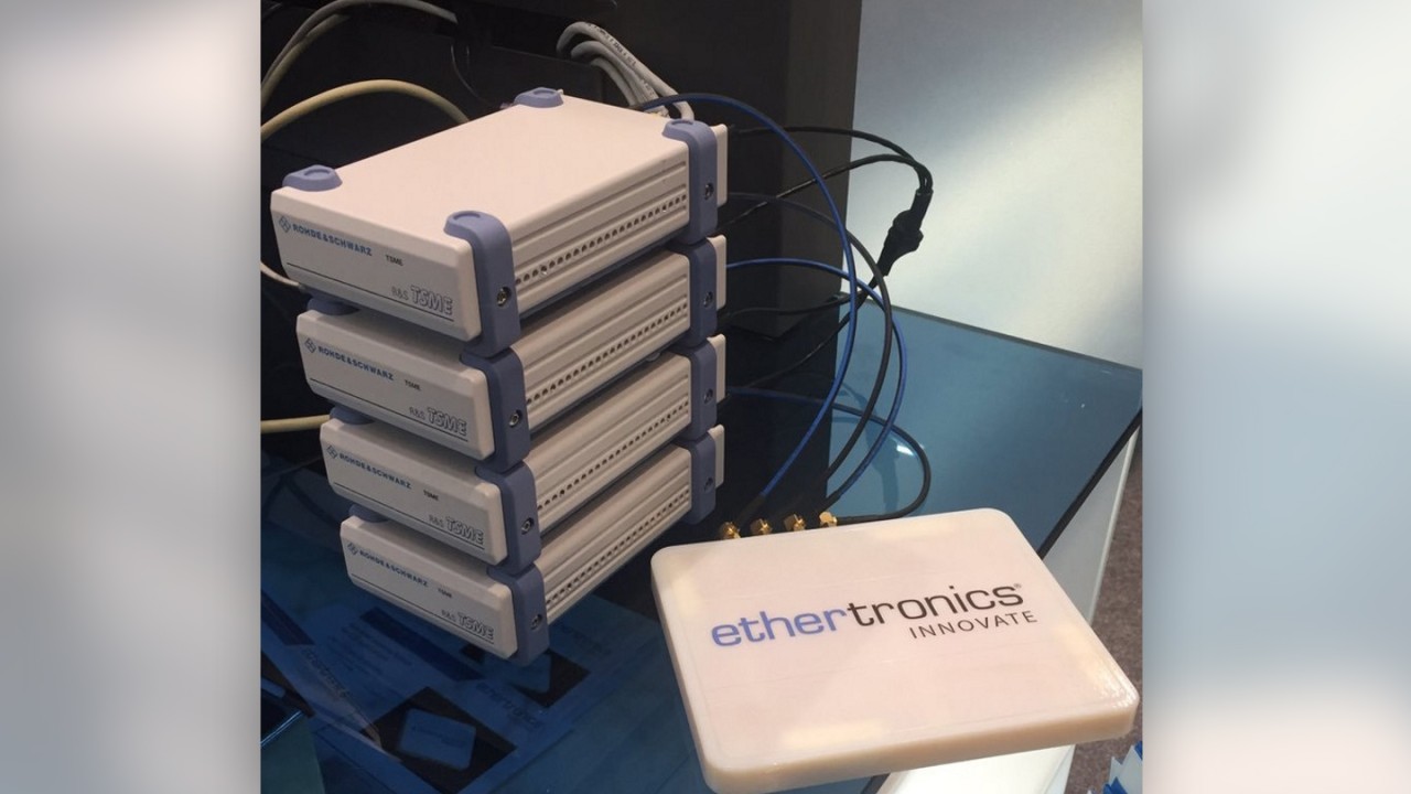
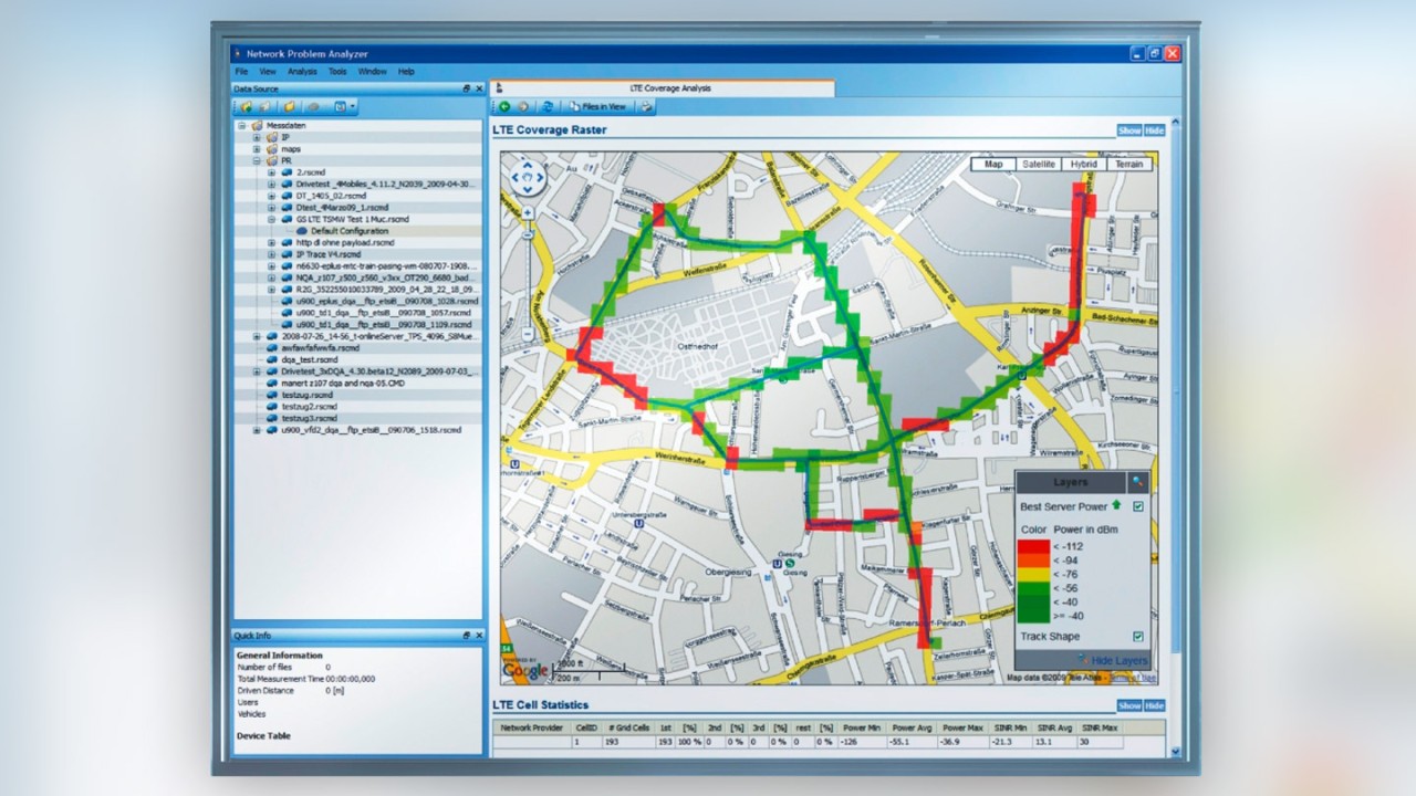
The following Rohde & Schwarz mobile network testing solution (consisting of 4 R&S®TSME scanners, a 4-receive antenna (prototype), and the R&S®ROMES4 analysis software) can measure or rather estimate the channel matrix components and calculate the rank and condition number of the channel matrix – a unique feature. With this feature set, mobile network operators can test different positions and identify typical environments in which 4×4 MIMO deployment is beneficial, offering a return on investment.


To learn more about 4x4 MIMO visit our dedicated web page here.


