Written by Oliver Jonas | September 14, 2017

In an earlier post, I talked about user roles. Here’s a quick summary of the main user roles in drive testing:
- The driver steers the car or follows a route with little or no configuration tasks, watches the system status, and, in case of an alarm, awaits remote problem resolution.
- The drive test engineer can be driving the car, configures the system in the car, starts the campaign for one or more cars, and can troubleshoot local problems if they arise.
- The back-office network engineer, who is not in the car and has profound knowledge of the network, technologies, and of the drive test software, manages test campaigns for potentially many cars.
It is impossible for a back-office engineer to constantly monitor a large test fleet in operation. Say, you had 20 test systems and 24 probes per system, then you would need to keep an eye on almost 500 individual measurement probes…
Fortunately, SmartBenchmarker offers a smart alarming implementation that continuously collects real-time status information from all systems, system components, and measurement probes. The implementation uses a set of rules to determine whether, when, and where an alarm notification is triggered and displayed. This frees up your back-office network engineers who can use the time to prepare the next measurement campaign.
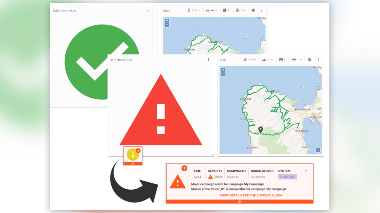
The requirements for a driver are different. A driver needs to focus on traffic and requires a straightforward “go” vs. “no go” representation of the system state, and a map showing the route to be driven and the current position. The SmartBenchmarker’s “Safe driver view” is a dedicated dashboard, created for precisely this purpose.
If an alarm is triggered, the user will see an intrusive pop-up that appears on any user interface (UI) element and across all connected systems. This means that as long as the system is connected, the driver, drive test engineer, and back-office engineer see the same alarm at the same time. The pop-up shows the number of alarms and can be tapped or clicked on to expand the full list of alarms and problem details, critical and major alarms being listed first.
Pop-ups of active alarms won’t go away unless the underlying problem is fixed or gets resolved by itself. A user may also hide or acknowledge alarms. For example, a particular measurement probe might have a hardware failure and should be silenced for the rest of the campaign. While hiding an alarm only hides it for the current user, acknowledging an alarm triggers a synchronization among the connected systems.
Let’s now have a look at the various concepts involved in the SmartBenchmarker’s alarming interface.
Campaign issues vs. alarms in SmartBenchmarker
There’s a subtle difference between what is reported as a campaign issue and a system alarm. Issues with campaigns are reported before a campaign is started and may be caused by an invalid campaign configuration or a missing precondition. Considering the latter, a campaign issue can be thought of as a condition or problem that would trigger an alarm if the campaign were running.
For example, a measurement probe that is selected for a test campaign may not be currently connected to the system. If the campaign is not running, then it is sufficient to indicate a campaign issue (a potential problem); the system should not yet trigger an alarm. Without the probe being connected, the campaign cannot start. If, on the other hand, the campaign is already running and a probe disconnects, it could mean a serious problem that affects ongoing measurements. In this case, the system will generate and show an alarm.
There are a few additional validations that are reported as campaign issues. For example, a probe may need a configuration update; it may require its system clock to be synchronized before the campaign is started, or it may be missing a license that is required for a particular test type.
Alarm severity levels
There are three types of alarm security levels in SmartBenchmarker:
Minor alarms represent warning conditions that do not necessarily disrupt ongoing measurement campaigns. A minor alarm may be triggered if the test system’s GPS device reports a low location accuracy or reports no valid position for a certain amount of time. This could happen in tunnels or in city blocks with many high rising buildings.
Major alarms represent error conditions that typically require some sort of action. A major alarm would be triggered if the GPS device or measurement probes suddenly disconnected or probes stopped measuring.
Even though unlikely to happen, let’s assume a fan inside a Test Device Containment Modules (TCM) stalled and would trigger a major alarm. Although the system would remain operational, it might not get cooled sufficiently. However, if the board’s thermal sensor reported a temperature of 85°C or higher, a critical alarm would be triggered. Such an alarm would require the driver’s immediate attention to prevent the system from overheating (the driver would have to interrupt the drive test and possibly power the system off).
SmartBenchmarker alarm types
Probe alarms
If a mobile or scanner probe becomes unavailable during a SmartBenchmarker measurement campaign or indicates that its state is no longer ‘Recording’, a major alarm will be raised immediately. Unless the system resolves the alarm itself, the test engineer should verify the problem, since the probe might be no longer recording data (figure 1).

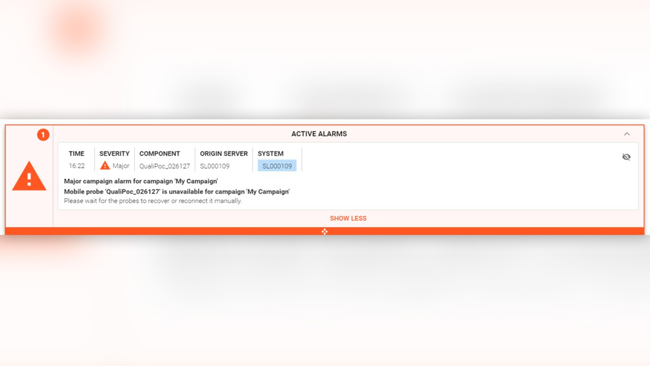
Fig 1: Major alarm indicating a missing measurement probe
Hardware alarms
Several hardware sensors built into the Vehicle Roof Box (VRB) and the Test Device Containment Modules (TCM) can be viewed in real-time through the SmartBenchmarker hardware controllers.
SmartBenchmarker comes with predefined thresholds that define the sensors’ operation limit. When a sensor detects an abnormal value, it immediately raises an alarm. These thresholds also define the severity of the alarm – major or critical. Critical alarms, such as alarms from thermal sensors (figure 2), should be immediately checked to avoid any hardware damage.

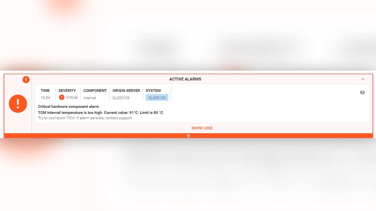
Fig 2: Critical alarm warning about excessive internal temperature
Location and time source alarms
GPS-specific alarms are immediately raised if no location or time source is selected or if the GPS device is physically disconnected. If the GPS device reports no valid position or bad accuracy and does not improve within 1 minute, an alarm will be raised (figure 3).

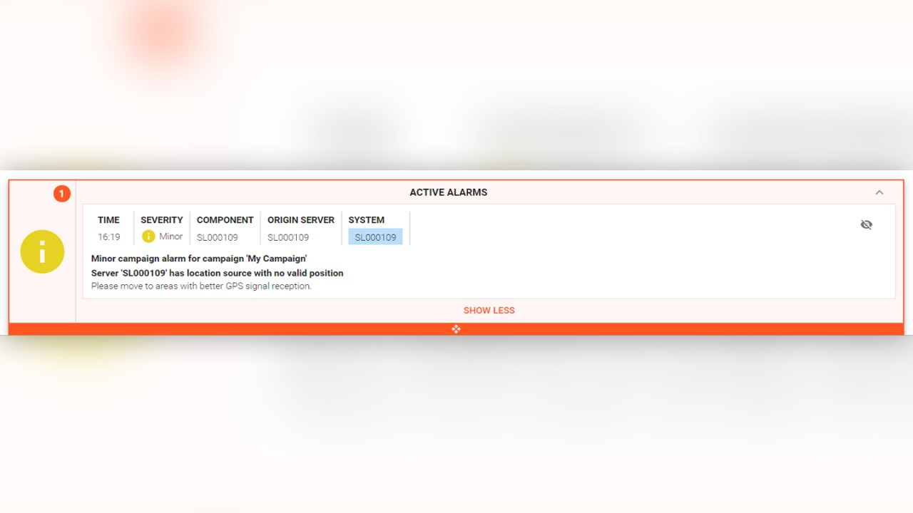
Fig 3: Minor alarm indicating that the GPS has no valid fix
System connection alarms
A SmartBenchmarker system can be scaled by connecting multiple system slaves to a system master and multiple system masters to a central master. Each slave may connect multiple measurement probes, and test engineers can start campaigns from the system master. The alarming interface monitors whether system slaves remain connected to the system masters (and system masters to their central masters) while measurement campaigns are running. An alarm is raised if the connection breaks (figure 4).

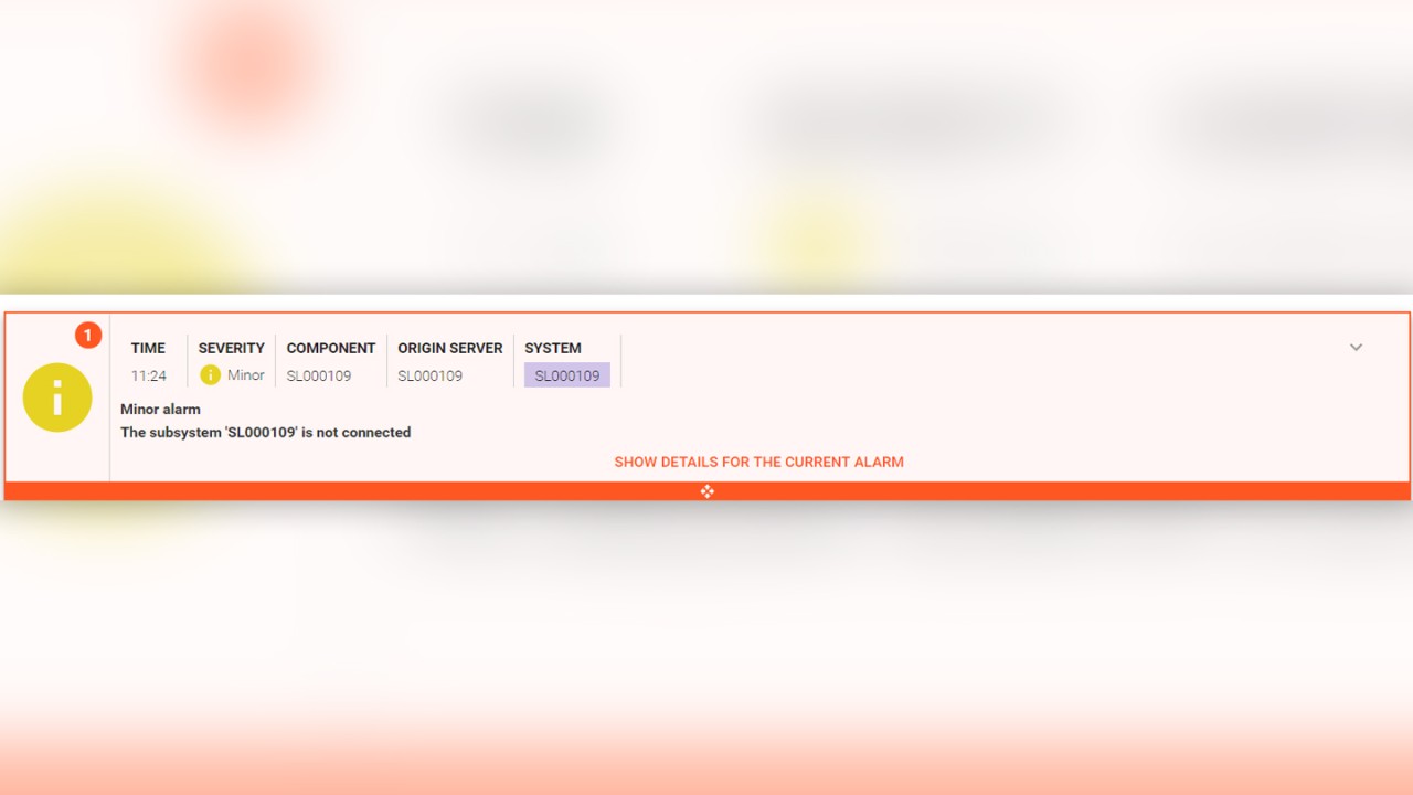
Fig 4: Minor alarm indicating a system slave has disconnected
Measurement file alarms
The alarming in SmartBenchmarker also keeps track of the whereabouts of measurement files. After all, the measurement files store the result of a day’s worth of drive testing and are therefore very valuable. Result file tracking starts as soon as a campaign has finished, and measurement probes report the result files’ availability. All result files will be automatically copied from the probes to their respective system slave or system master.
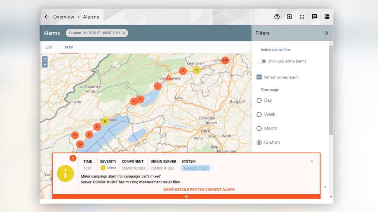
When all the files have been copied to a system slave, they will need to be forwarded to the system master. Once all tracked files have arrived on the system master, an SQC container is automatically created, containing the measurement campaign’s result files. If there is a connection error or other file transfer problem, users will see an alarm showing the details of the missing measurement files, including probe, server, and system name (figure 5). The alarming rules take into account the size of result files when estimating the time needed to deliver results files from probe to system master.

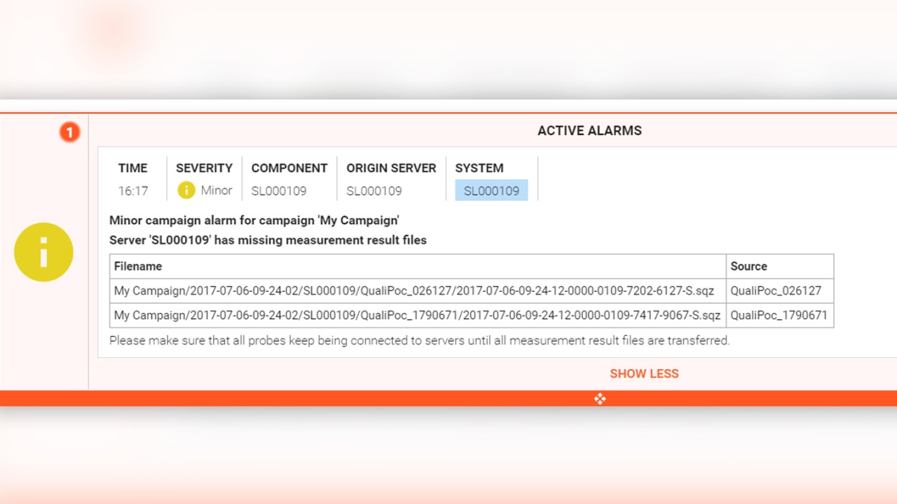
Fig 5: Alarm showing missing measurement files
Alarm tracking & history
All alarms are recorded in a database and can be viewed and filtered in a variety of ways (active alarms only, by date and time, or by severity, component type, and source). Most importantly, alarms can also be viewed by the system, which is crucial for back-office test engineers who remotely monitor drive tests across various systems.
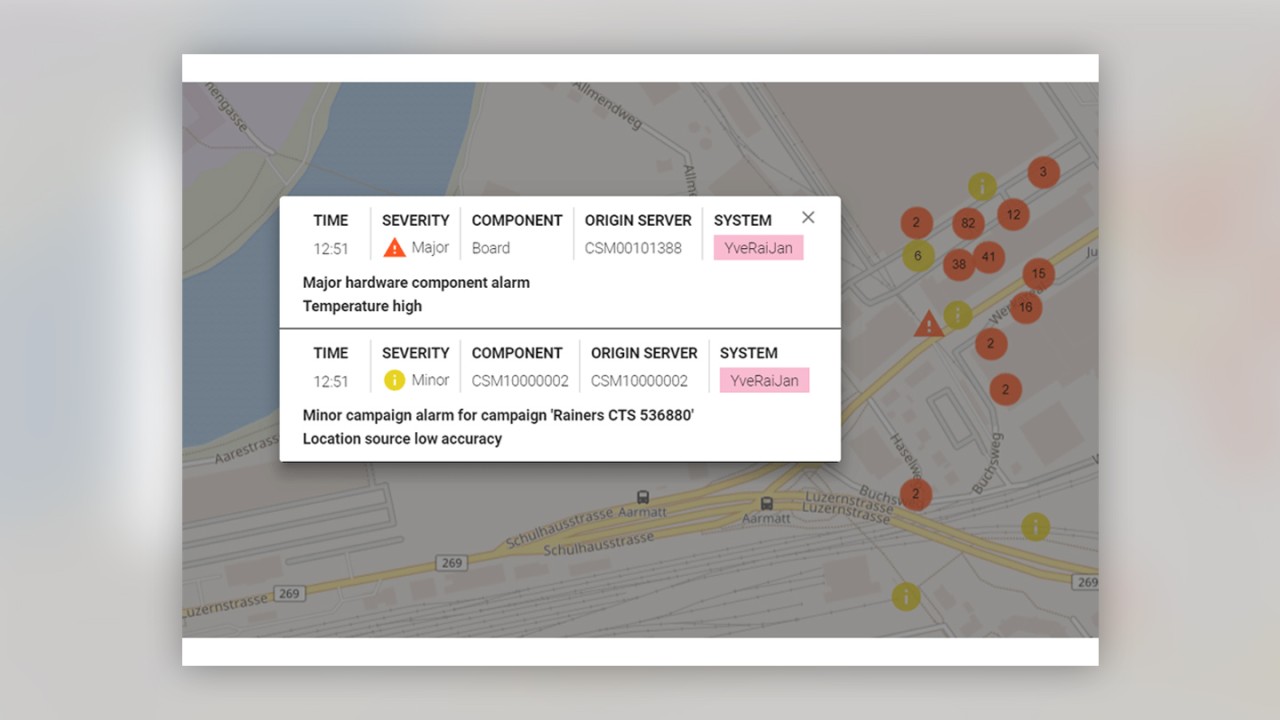
As long as the cause of an alarm is not a poor GPS reception, alarms can also be tracked geographically and displayed on a map. This is a useful tool for reviewing problems that were encountered during a drive test along a given route. The alarms can be plotted on a map either remotely or in real time while the drive test is still in progress. If a problem is deemed serious but fixable, the back-office test engineer can advise the driver to return and repeat the drive of a specific route segment.
The map view displays alarms in clusters. This means that if there are many alarms recorded nearby, you will see the alarms grouped by severity with the total alarm count shown for that area. By zooming in on the map, you can expand the cluster and view details about individual alarms in this area.
By tapping or clicking an alarm, you can also see full details about the alarm at that location.
Vehicle Roof Box schema
The Vehicle Roof Box (VRB) can contain up to 16 Test Device Containment Modules (TCM) and ensures uniform RF and temperature conditions through controlled air cooling/heating, making it ideal for large-scale measurements in any weather condition.
SmartBenchmarker offers a dedicated schematic view of the VRB, allowing test engineers to set up and view the mounting positions of the TCMs and their measurement probes. When operating a fleet of vehicles with many systems connected to a central master, it’s possible to remotely manage and visualize multiple VRB configurations in real time.
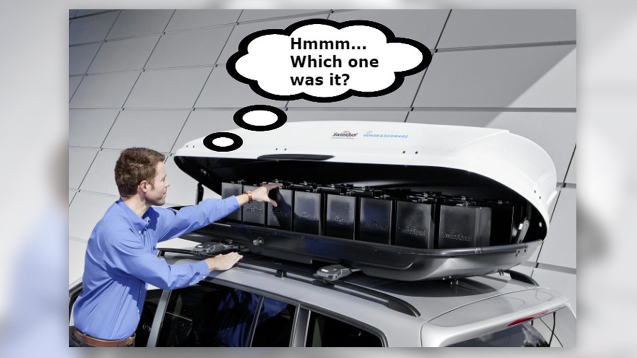
In case a problem with a probe requires manual intervention and physical access to the device inside the TCM, the schematic view makes it easy for the drive test engineer to locate the mounting position of the probe. Equally, the back-office network engineer remotely monitoring a drive-test can guide the driver in locating the affected TCM and even suggest further action, such as rebooting the device inside the TCM.

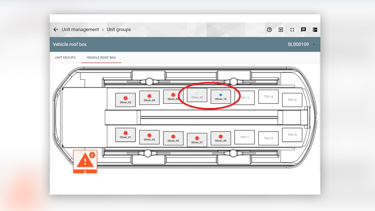
Fig 7: VRB schematic view showing the mounting positions of two problematic probes
With dedicated user roles and reliable alarming functionalities that are synchronized across all connected systems and can be managed remotely, drive test benchmarking with SmartBenchmarker offers mobile network operators and service providers more flexibility and simplicity when setting up and managing large-scale measurement campaigns in an increasingly challenging and complex RF environment.


