Test and measurement

Enhancing channel-to-channel alignment for accurate phase-coherent multichannel acquisition

Thanks to their multichannel capability, oscilloscopes are ideal for multichannel applications such as the analysis of MIMO signals (e.g. 5G NR, WLAN), multi-antenna radar signals and differential high-speed digital signals (e.g. USB 3.x). These applications require the oscilloscope channels to be tightly aligned. This means the channel-to-channel residual skew has to be measured accurately so that it can be compensated. The channel-to-channel phase mismatch is reduced to a minimum, which plays a crucial role in achieving reliable measurement results.

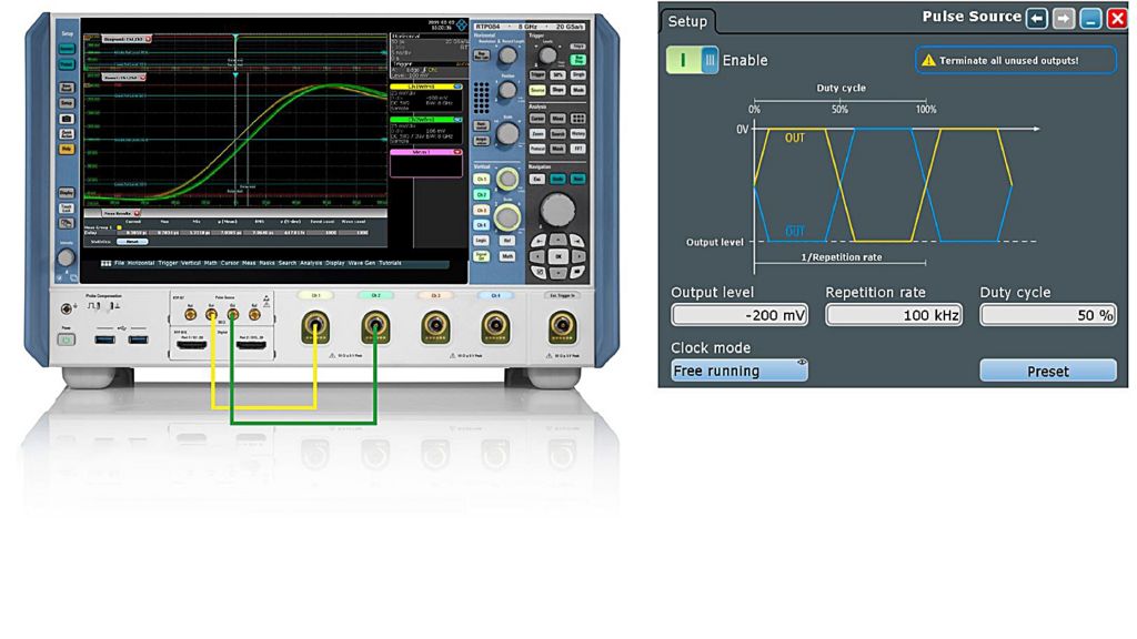
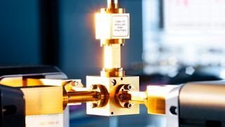
Fig. 1: Measurement setup
Open Lightbox

Your task

This application card shows how to measure the channel-to-channel skew and compensate it across the entire signal path between the signal source and the oscilloscope channel input when using the high-speed differential pulse source available for the R&S®RTO and R&S®RTP oscilloscopes (R&S®RTO-B7/R&S®RTP-B7 option required).

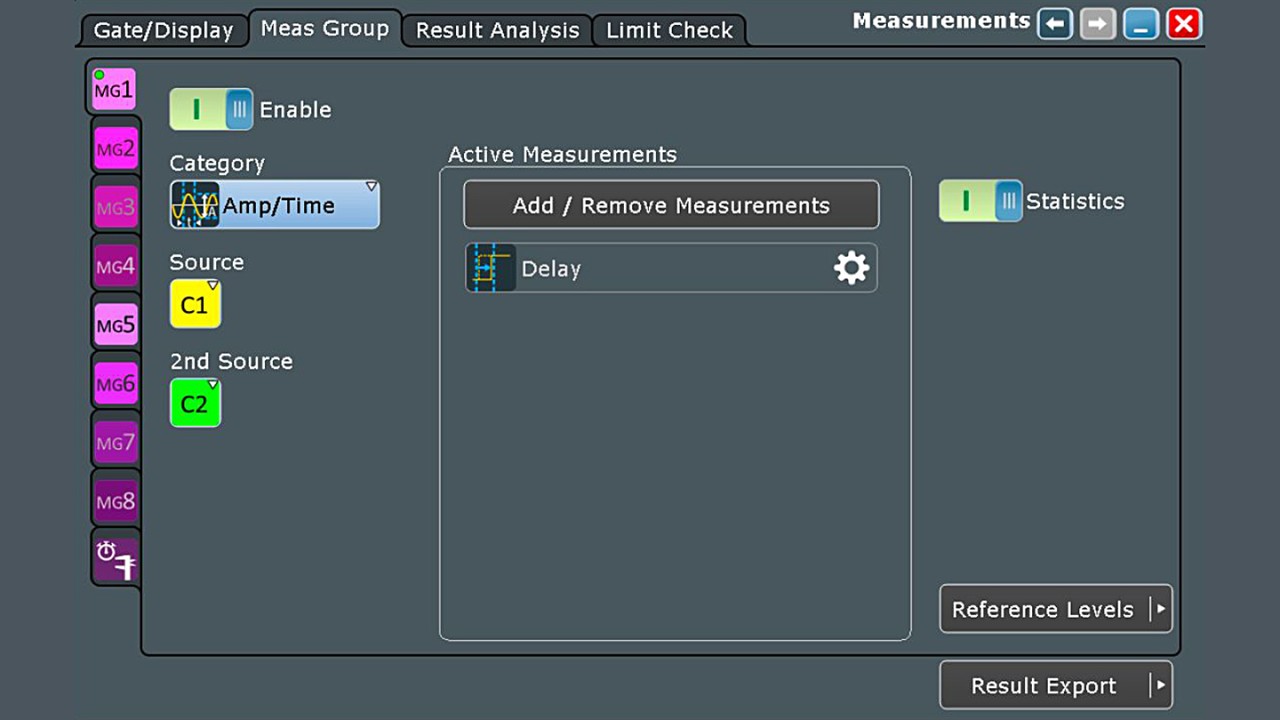
Fig. 2: Delay measurement settings
Open Lightbox

Rohde & Schwarz solution

With a skew of < 0.5 ps between its differential outputs, the R&S®RTO-B7/R&S®RTP-B7 option is an accurate source for deskewing a multichannel measurement setup. To correct for any skew in the test setup, connect the set of cables that you use for the measurement to the R&S®RTO-B7 outputs. Then feed them into both oscilloscope channels and measure the channel-to-channel skew. The measurement setup is shown in Fig. 1.

Due to the differential nature of the signals generated by the R&S®RTO-B7/R&S®RTP-B7 option, one of the inputs has to be inverted. It is then possible to measure the delay between two rising edges of the input signals using the corresponding automated measurement function (Fig. 2). Another approach consists of measuring the delay between a rising edge of one signal and a falling edge of the other. In this case, no inversion is needed. However, since it is more intuitive to compare two pulses having the same shape, the first approach explained above is recommended. By activating the statistics during the measurement, you can obtain the mean value of the channel-to-channel skew and use this value as a skew offset to perform the deskew.

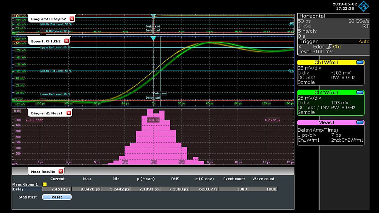
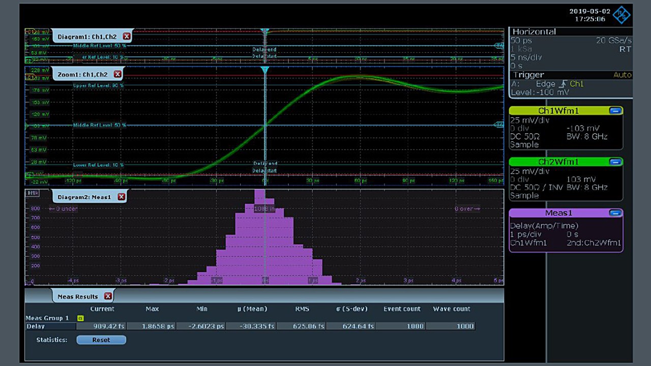
Fig. 3: Measured channel-to-channel skew with histogram and key statistical metrics
Open Lightbox

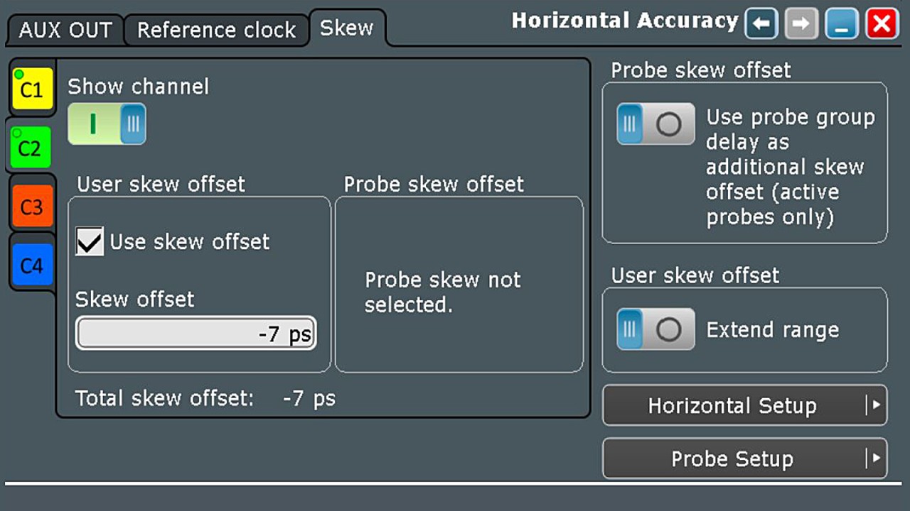
Furthermore, it is possible to plot the histogram of the measured delay to determine its statistical distribution. Fig. 3 shows the result obtained before deskewing the channels. Once the mean value of the skew is determined, it can be applied as skew offset in the probe settings as shown in Fig. 4. The result can be seen in Fig. 5, which clearly shows that the channels are aligned and the skew mean value is now < 1 ps.

Once the alignment has been performed, it is stable over the long term and valid after a restart and warm-up. This is due to the R&S®RTO and R&S®RTP oscilloscopes’ sophisticated temperature management. Please note that the alignment only remains valid if the same cables that were used during the deskew procedure are also used for the measurements.

Fig. 4: Deskew settings for channel 2
Open Lightbox

Application

Phase-coherent acquisition of:

  • RF MIMO signals (e.g. 3GPP LTE/5G, IEEE 802.11ac)
  • Multi-antenna radar signals

Tightly aligning channels for:

  • Differential high-speed digital signals (e.g. USB 3.x)
  • Parallel high-speed interfaces (e.g. DDR4)
Fig. 5: Measured channel-to-channel skew with histogram and key statistical metrics after deskewing
Open Lightbox
Related solutions