Hardware-in-the-loop testing with GNSS receivers made easy
The hardware-in-the-loop options for the R&S®SMBV100B and the R&S®SMW200A GNSS simulators enable realistic, cost-efficient and flexible testing in a user-controlled environment.

The hardware-in-the-loop options for the R&S®SMBV100B and the R&S®SMW200A GNSS simulators enable realistic, cost-efficient and flexible testing in a user-controlled environment.


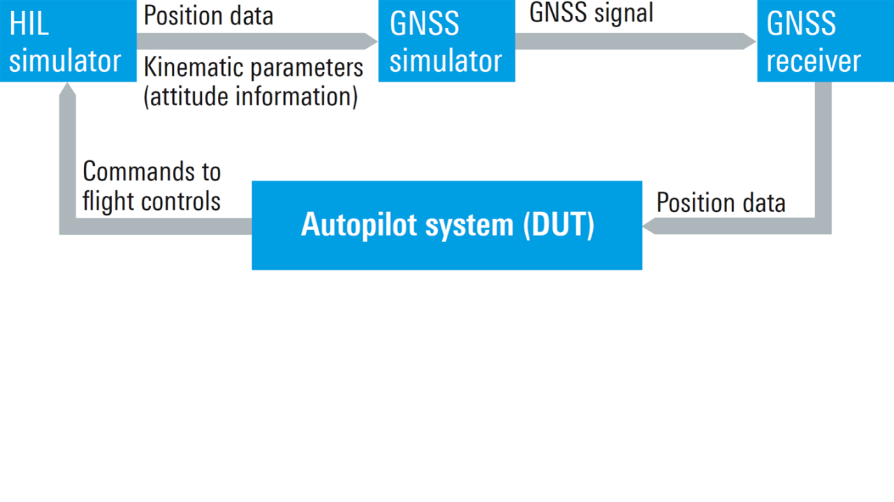
Fig. 1: Hardware-in-the-loop (HiL) test setup
Developing new, integrated GNSS-based systems for automotive and aerospace & defense applications is no easy task. These systems have to work reliably, accurately and under adverse conditions, which leads to the need for exhaustive testing and verification. Unfortunately, field testing is rarely an option for these complex systems. Realworld trials are slow and expensive, and there are limits to testing due to safety considerations. Development and testing of new GNSS reliant avionics systems, e.g. flight management and autopilot systems, are good examples since they involve all of the problems mentioned. Flight tests are expensive, and testing new, unproven systems in the air is prohibitively dangerous. Instead, it would be desirable to conduct testing in a lab environment.
Hardware-in-the-loop (HiL) test systems provide a realistic environment for the DUT, allowing its performance in the overall system to be evaluated in a closed loop in realtime.
Fig. 1 shows a HiL system that can be used to test an autopilot system. The HiL simulator calculates the position and orientation of the DUT, and the GNSS simulator generates the corresponding satellite signals, all controlled in realtime. The GNSS receiver provides position data to the autopilot system (DUT), which calculates flight control inputs based on this data. The output of the autopilot system, in turn, is validated in the HiL simulator.


R&S®SMBV100B integrated in HiL test setup
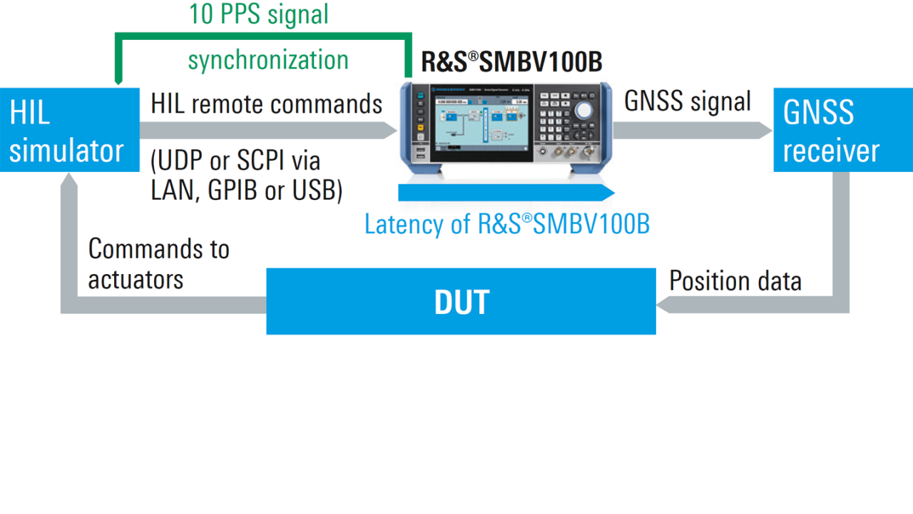
The R&S®SMBV100B and the R&S®SMW200A GNSS simulators can be equipped with a GNSS realtime interface option. This enables easy integration into a HiL test system to provide GNSS signals for the DUT. Fig. 2 shows a typical HiL test setup with an R&S®SMBV100B.
Easy integration thanks to flexible interface
To achieve maximum flexibility within a test setup, remote commands can be streamed over a LAN, USB or GPIB interface. Trajectory data is transferred to the GNSS simulator using SCPI or UDP commands. The GNSS simulator accepts realtime, six degrees of freedom (DoF) trajectory data, including receiver position, velocity, acceleration and attitude data (yaw, pitch and bank). Position updates can be sent at a fast update rate of up to 100 Hz. In conjunction with the low latency of the R&S®SMBV100B (down to 20 ms), low overall system latency and high processing and signal accuracy are achieved.
In a HiL simulation, accurate synchronization of all devices is necessary. The Rohde & Schwarz GNSS simulators provide a 1 PPS (pulse per second) or 10 PPS signal for reliable time synchronization with the HiL simulator. For more convenient operation and an optimized setup, the GNSS simulators offer comprehensive statistics and debug facilities.
Testing under realistic conditions
The Rohde & Schwarz GNSS simulators support a large number of GNSS channels (up to 144) as well as multiconstellation and multi-frequency setups, allowing even the most complex test scenarios to be generated. The simulated movement is continuously adjusted in realtime. Additionally, satellite visibility and power levels can be changed on the fly, offering enhanced possibilities for system testing, like modeling obscured and blocked GNSS signals.
To make simulations as realistic as possible, the GNSS simulator can take into account the antenna position, orientation and type. The antenna position can be configured in all six DoFs. Signal attenuation and blockages resulting from the mounting location of the antenna can be specified in a so-called body mask file supplied by the user. Additionally, a specific antenna pattern can be imported to model the exact type of antenna used. When attitude data is supplied to the GNSS simulator, the antenna pattern and body mask are used to accurately calculate the changes in the received signal for each satellite, just as it would occur in a real, dynamic scenario.


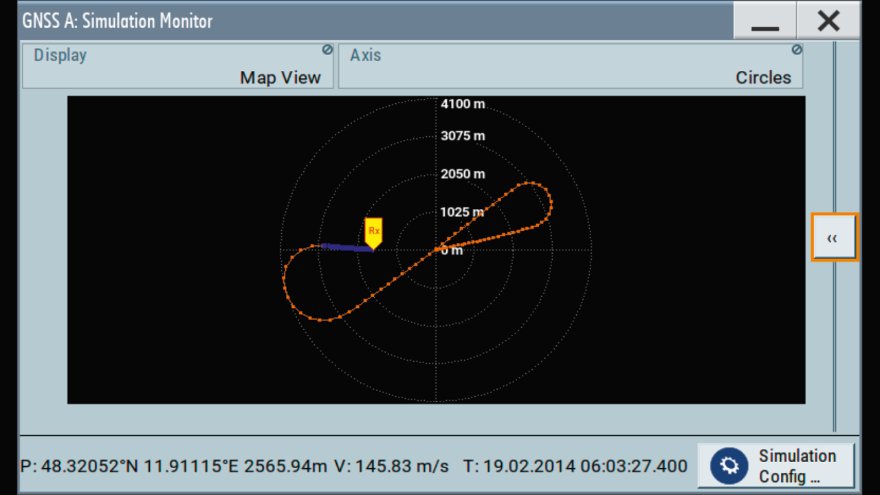
GNSS simulator GUI: realtime trajectory visualization.
Convenient user interface
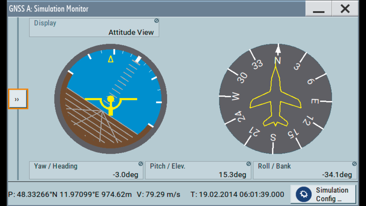
For the example discussed here, an R&S®SMBV100B is interfaced with a flight simulator to demonstrate the realtime trajectory data input to the R&S®SMBV100B. The flight simulator provides position, kinematic and attitude information to the GNSS simulator in realtime, and the GNSS simulator calculates the corresponding GNSS signals according to the trajectory. Below, the trajectory of the plane is displayed on the GNSS simulator GUI in realtime, along with important parameters like position and velocity.
Attitude information can be visualized on an artificial horizon and a compass, which allows easy checking of the simulated parameters. This is especially useful when an antenna pattern is used to simulate a certain type of receiver antenna. With either instrument, the current orientation of the antenna can be determined instantaneously.

