Verify radio performance of IEEE 802.11be devices
RF performance measurements for Wi-Fi 7.

RF performance measurements for Wi-Fi 7.


Development of next generation Wi-Fi standards is now in full swing as seen in the current draft of the IEEE 802.11be specification, which has already been defined enough on the physical layer for specific implementations. Signal generators and signal analyzers help open up the Wi-Fi 7 signal world and allow initial component and module testing for this new standard.

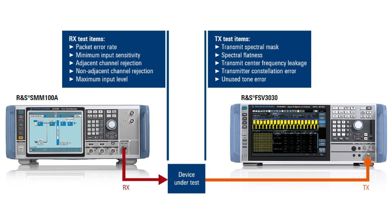
Typical test setup for IEEE 802.11be device testing with R&S®SMM100A vector signal generator and R&S®FSV3030 signal and spectrum analyzer.
The next generation of Wi-Fi The latest IEEE 802.11ax Wi-Fi standard was defined to improve efficiency and support a wider range of use cases such as large venues where several connected devices are active at the same time. Technology cornerstones include the introduction of OFDMA, 78.128 kHz sub-carrier spacing, longer guard intervals and 1024QAM as highest possible modulation scheme.
The new standard focuses on high data throughput at low latency for applications in homes, offices and factories.
Two practical approaches help to improve data throughput on the physical link layer: applying higher modulation schemes and more flexible use of allocated frequency spectra, especially in environments with high user density.
IEEE 802.11be incorporates both approaches and also specifies higher MIMO schemes. The new standard is based on IEEE 802.11ax and consistently follows its approach. For example, signal bandwidths are increased up to 320 MHz to leverage the greater spectrum availability in the 6 GHz band, new modulation schemes up to 4096QAM are possible along with parallel transmission of up to 16 data streams. Allocating multiple frequency blocks (multiple resource units, MRU) to a user allows more efficient use of a spectrum and access point connections that are better tailored to data-hungry clients.
The new standard will introduce multilink operation (MLO)that aggregates several physical links for improved data throughput, latency and reliability.
These extensions collectively enable extremely high throughput (EHT) as defined in IEEE 802.11be specifically for IEEE standards.
IEEE 802.11be defines two new physical layer protocol data unit (PPDU) formats with a new preamble to ensure long term application and backward compatibility. Along with EHT-specific fields for control data, each preamble contains some legacy fields for backward compatibility with earlier IEEE 802.11 standards.
Instruments must be able to handle the new PPDU formats and meet more demanding physical requirements.
|
Wi-Fi 5 IEEE 802.11ac very high throughput (VHT) |
Wi-Fi 6/6E IEEE 802.11ax high efficiency (HE) |
Wi-Fi 7 IEEE 802.11be extremely high throughput (EHT) |
|
|---|---|---|---|
| Supported bands | 5 GHz | 2 GHz, 5 GHz, 6 GHz | 2 GHz, 5 GHz, 6 GHz |
| Channel bandwidth |
20 MHz, 40 MHz, 80 MHz, 80 MHz + 80 MHz, 160 MHz |
20 MHz, 40 MHz, 80 MHz, 80 MHz + 80 MHz, 160 MHz |
20 MHz, 40 MHz, 80 MHz, 160 MHz, 320 MHz |
| Transmission scheme | OFDM | OFDM, OFDMA | OFDM, OFDMA |
| Subcarrier spacing | 312.5 kHz | 78.125 kHz | 78.125 kHz |
| Guard interval | 0.4 μs, 0.8 μs | 0.8 μs, 1.6 μs, 3.2 μs | 0.8 μs, 1.6 μs, 3.2 μs |
| Spatial streams | 8×8 (incl. DL-MU-MIMO) | 8×8 (incl. MU-MIMO) | 16×16 (incl. MU-MIMO) |
| Modulation (highest) | 256QAM (8 bit) | 1024QAM (10 bit) | 4096QAM (12 bit) |
Generating IEEE 802.11be signals
An IEEE 802.11be signal generation solution must meet two conditions: support for 320 MHz signal bandwidth for all EHT transmission modes and 4096QAM signal generation capabilities in the 6 GHz band (5.925 GHz to 7.125 GHz). Generator EVM performance must be lower than –50 dB when testing power amplifiers and receivers. The high-end R&S®SMW200A and mid-range R&S®SMM100A vector signal generators meet these requirements.
This requires two options: the R&S®Sxx-K54 Wi-Fi base option that enables signal generation in line with IEEE 802.11a/b/g/n/j/p along with the additional R&S®Sxx-K147 option that includes new features for IEEE 802.11be.

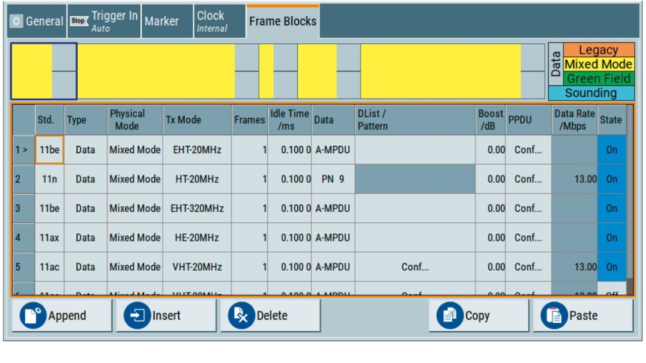
Wi-Fi configuration with the R&S®Sxx-K54 option
Quick and easy PPDU configuration
IEEE 802.11be signals can be configured in just a few steps. First, select the transmission mode in the frame block sequencer and then configure the PPDU.
As mentioned above, IEEE 802.11be introduces new PPDU formats (EHT MU and EHT TRIG) which contain U-SIG and EHT-SIG fields specific to IEEE 802.11be with legacy training and signaling fields. Some signaling data, including the PHY version identifier, is preconfigured. Other parameters, such as link direction, PPDU type, BSS color, STA-ID, MCS type and channel coding can be directly and clearly selected in the PPDU configuration dialog.
The menu-driven settings for resource unit allocation and punctured channels are applied indirectly to EHT-SIG and U-SIG. The IEEE 802.11be option allows multiple resource units (MRU) to be allocated to an individual user.
Resource units can have 242, 484 or 996 subcarriers, which determine how many channels can be allocated to a user. The MRU index defines the resource unit positions inside the channel.
Specific frequency ranges within the signal bandwidth, occupied by privileged applications such as weather radars are automatically excluded and not used for transmission. After selecting the standard (first column), the configuration menu can be used for further settings.

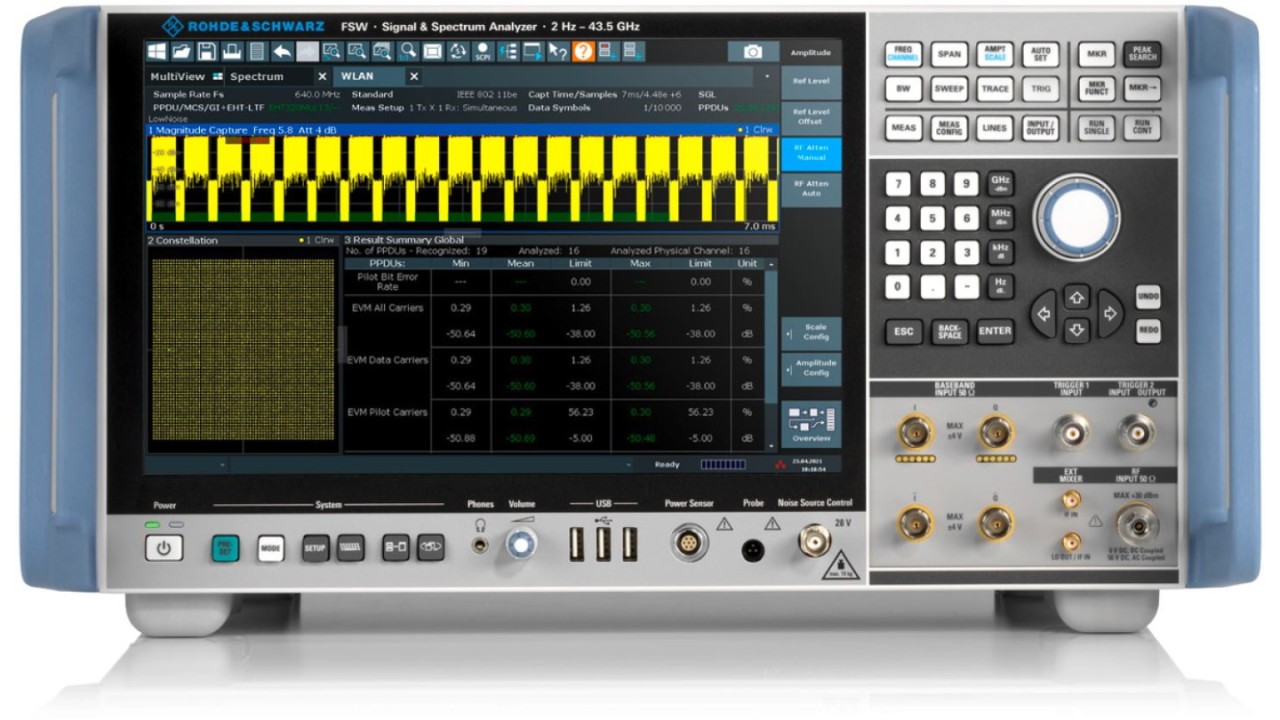
R&S®FSW high-end signal and spectrum analyzer
Spatial mapping
To increase data throughput, IEEE 802.11be specifies up to 16 parallel data streams for both SU-MIMO (16×16) and MU-MIMO for up to eight simultaneous stations and up to four data streams for each user. The R&S®SMW200A and R&S®SMM100A calculate all the data streams with onboard resources, two of them can be output simultaneously over the R&S®SMW200A RF interfaces.
Analyzing IEEE 802.11be signals
The R&S®FSx-K91BE measurement option adds IEEE 802.11be capabilities to existing IEEE 802.11a/b/g/n/p/ac/ad/ax/ay measurement options for the high-end R&S®FSW and mid-range R&S®FSV3000 signal and spectrum analyzers.

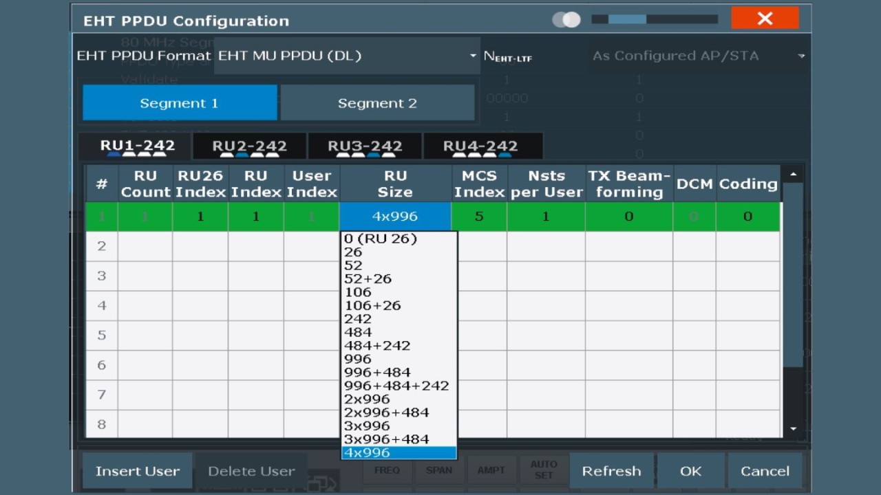
Menu for manual resource unit allcoation and user-specific indices
Two approaches to setting up an analysis
One uses the PPDU format configuration menu to define signals that do not fully comply with the standard, which can be interesting in the early stages of standardization.
A more convenient approach involves auto demodulation and auto detection to configure parameters such as EHT long training field (EHT LTF) lengths and the guard intervals. In auto detection mode, the analyzer is automatically configured for an applied IEEE 802.11be signal and lists the parameters. Resource unit allocation, the modulation and coding scheme (MCS) and other user-specific values can also be defined in the new U-SIG (universal SIG) and EHT-SIG signal fields.

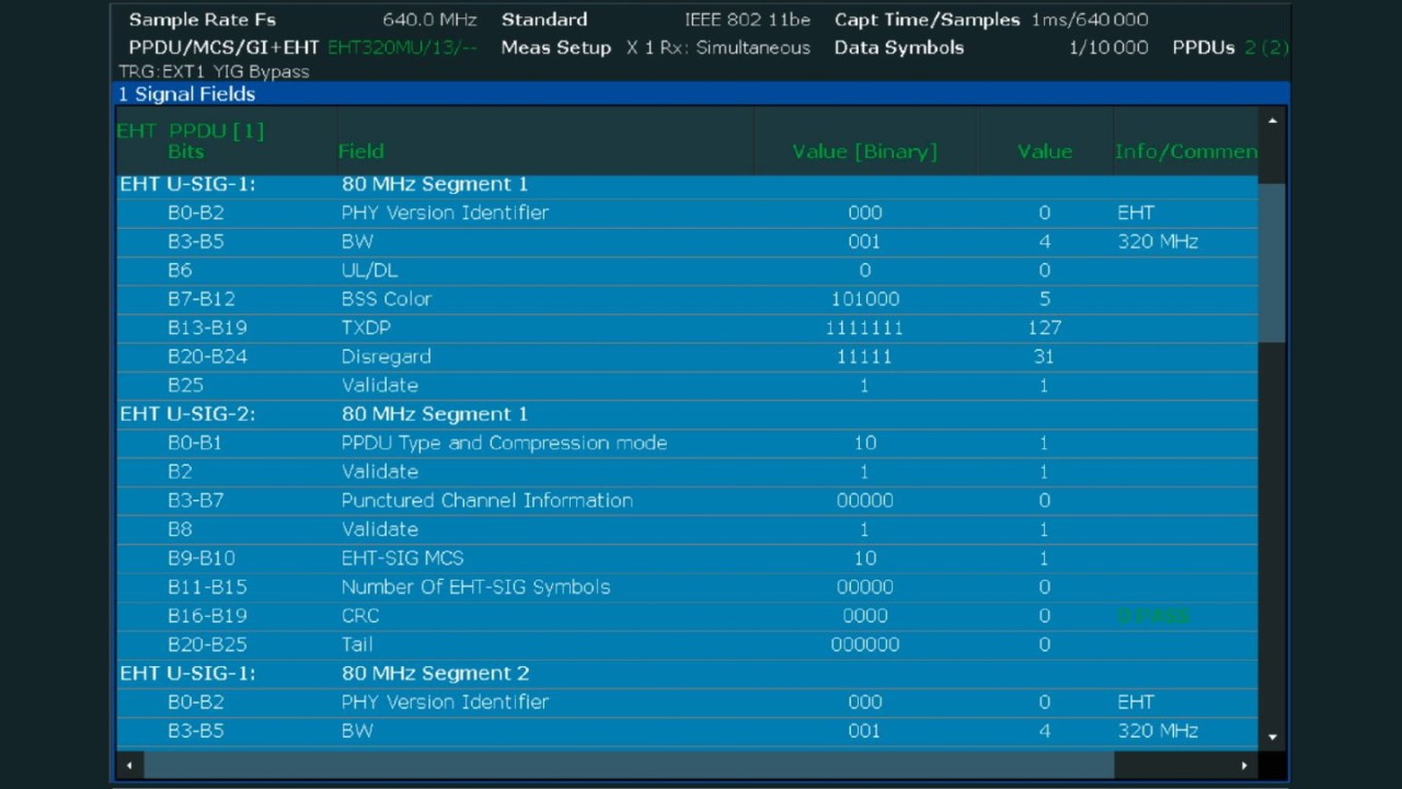
Parameter list from IEEE 802.11be signal auto detection
The new 4096QAM modulation and coding schemes, as well as signal bandwidths up to 320 MHz set greater demands on signal quality than in the past. IEEE 802.11be requires a maximum EVM of –38 dB for both multi-user PPDUs (EHT MU PPDU) and trigger based PPDUs (EHT TB PPDU). The analyzer should typically be able to measure the EVM accurately down to at least –48 dB with a safety margin of 10 dB. The R&S®FSW-B320 option for 320 MHz analysis bandwidth makes this possible for the R&S®FSW.