Verifying the clock source
The signal purity of clock sources has a direct impact on system performance. To ensure proper operation, it is necessary to verify that the purity meets the design requirements.

The signal purity of clock sources has a direct impact on system performance. To ensure proper operation, it is necessary to verify that the purity meets the design requirements.
As a designer of analog and digital circuits, you use and rely on the clock signal used in the target system. Since the clock directly influences overall system performance, it is essential that its performance be good enough to meet the needed requirements.
In order to select or develop a clock generator to use in your design or to ensure that the supplied system clock has the proper performance once it reaches your section, you need to verify its performance to make sure it meets your needs. Phase noise, jitter, wideband noise and spurs are typical performance indicators.


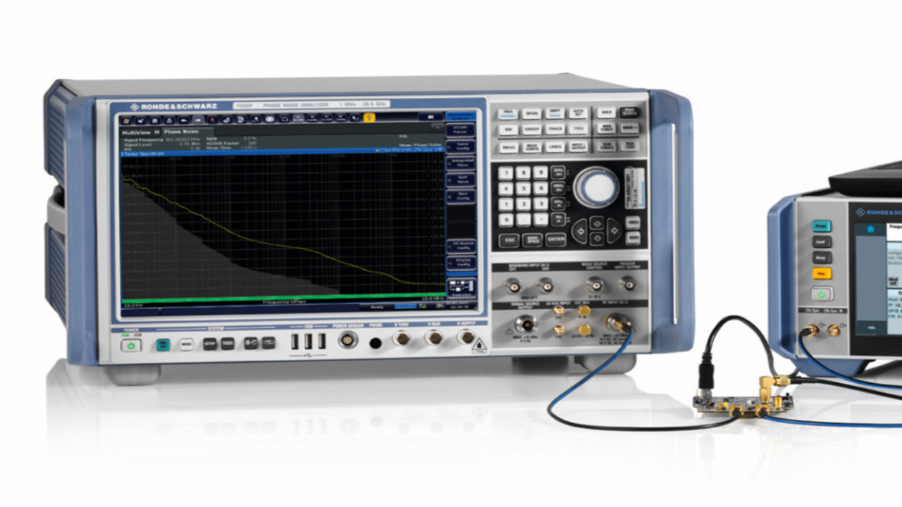
Measuring the phase noise and jitter of the clock source with the R&S®FSWP.
The R&S®FSWP phase noise analyzer and VCO tester is the right tool for verifying clock sources. Clock jitter is typically measured in the time domain. For superior sensitivity, users switch to the frequency domain to measure the clock jitter based on a phase noise measurement. The frequency domain approach also makes it easy to separate random jitter from periodic jitter, which can be easily determined by the spur level. Easily changeable integration ranges and weighting filters make it an even more powerful tool for jitter characterization with highest sensitivity.


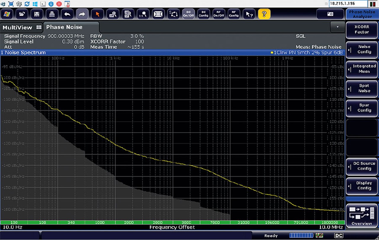
The R&S®FSWP displays the achievable level of sensitivity with grey color-coding.
For measuring clocks with very low jitter, the R&S®FSWP can be equipped with a second internal local oscillator to allow cross-correlation and improve the phase noise sensitivity. To know how many correlations are useful, the instrument displays the achievable level of sensitivity with gray color-coding for a given setting. If the gray area is clearly below the trace, you know that the measurements are correct. Thanks to the extremely low-noise internal sources, only a small number of cross-correlations are needed to achieve a large sensitivity range. This speeds up measurement of clean signals dramatically.
In addition to the R&S®FSWP high-end T&M solution, a mid-range instrument is also available. The R&S®FSPN phase noise analyzer and VCO tester offers phase noise measurements including cross-correlation, Allan variance determination and VCO characterization for tighter budgets.
The R&S®FSWP key facts
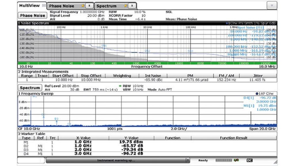
A spectrum analyzer is typically used for spur searches. The R&S®FSWP includes a high-end spectrum and signal analyzer covering the full frequency range of the phase noise tester. You can search for spurs in the spectrum analyzer mode without any other instruments. Thanks to the large screen, you can configure multiple result windows in parallel on the display – and see the result of the phase noise measurements and the spectrum side by side.
The R&S®FSWP features
The R&S®FSWP includes a useful add-on as standard: low‑noise internal DC sources for VCO characterization. It includes a power supply up to 16 V and a tuning voltage supply up to 28 V. Therefore, the power supply for the clock source module comes free. If the clock source is frequency tunable and based on a VCO design, tests over supply and tuning voltages are easily performed. The R&S®FSWP is the right tool for verifying the performance of the cleanest clock sources to ensure that the clock does not affect overall system performance. The R&S®FSPN is available in addition as a more economical alternative.


Phase noise measurement and spur/harmonic search in the spectrum domain in parallel.