Written by Magnus Hylén | June 07, 2023

Overview
The arrival of 5G New Radio (5G NR) has made radio network layouts much more complex than they were for legacy 4G/LTE networks.
Fully new frequency band ranges (including mmWave) and new network architectures that allow dual connectivity create new opportunities but also pose challenges for radio network design as well as the analysis and optimization of these networks.
User equipment (UE) can either connect standalone over LTE or 5G NR networks and over both with non-standalone connectivity.
5G has greater flexibility, making it even more challenging to understand and analyze radio networks. With the growing number of network interfaces and radio access network (RAN) configurations, system experts and radio engineers need more expertise and develop methods and tools to optimize or troubleshoot 5G and 4G networks.
Analytical challenges
We are going to take a closer look at radio resource control (RRC) layer 3 signaling in 5G NR and 4G LTE mobile networks and analyze the connection control, measurement configuration and mobility procedures.
The RRC reconfiguration message contains vital information. The message can include measurement configurations, handover information, as well as add and release cells for carrier aggregation and dual connectivity.
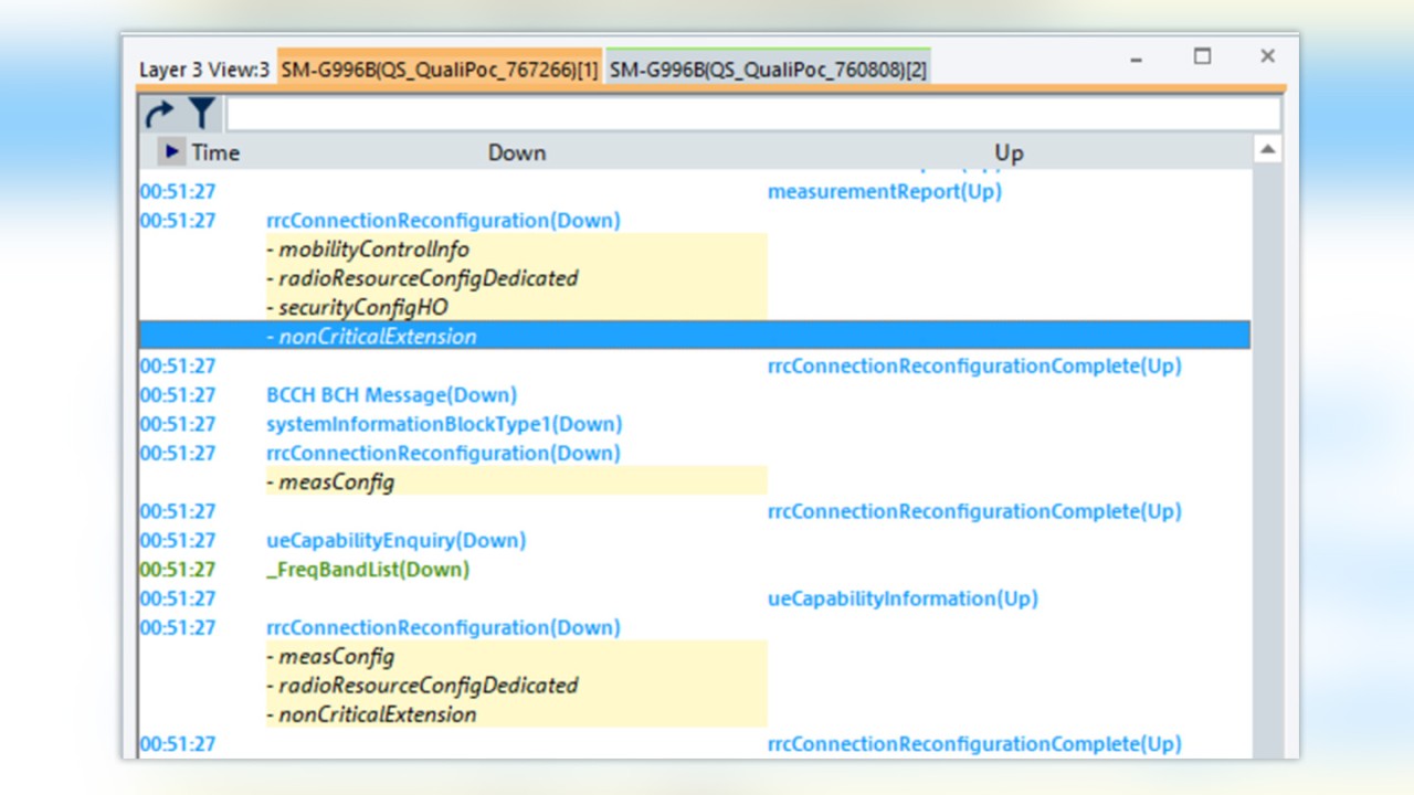
A sample RRC layer 3 LTE protocol analysis:
The sequence starts with a measurement report from the UE in the uplink followed by an RRC connection reconfiguration message in the downlink. The underlying procedures can be found in the message content and you need to be a 3GPP protocol expert to decipher all the important information.
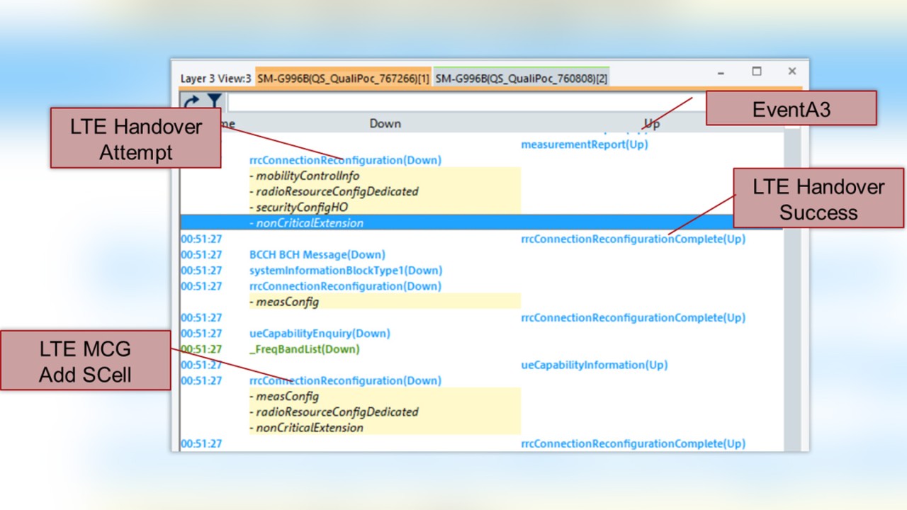
LTE and 5G NR RRC reconfiguration messages are some of the lengthiest in the protocol stack and it can take time to fully understand them. A protocol expert can decipher these messages and gain the insight seen in the screenshot below:
1. The measurement report is triggered by a previous Event A3 reporting configuration. The LTE RAN will act upon the Event A3 message and initiate a handover attempt that is signaled by the RRC reconfiguration message.
2. Analyzing the extension fields in the next RRC reconfiguration message confirms that adding SCells will activate carrier aggregation.
This is just one RRC signaling sequence out of the hundreds that a device can generate over the course of an hour and analyzing them all is tiresome work, even for experts.
The solution – let the tool be the expert
Letting a tool such as R&S®ROMES4 do the work for you is a smart alternative. The built-in expert decoder extracts RRC message information and automatically translates it into the structured RRC connection control, measurement and mobility functions, presenting them as RRC events and key performance indicators (KPI) along with all other logged UE diagnostic information.
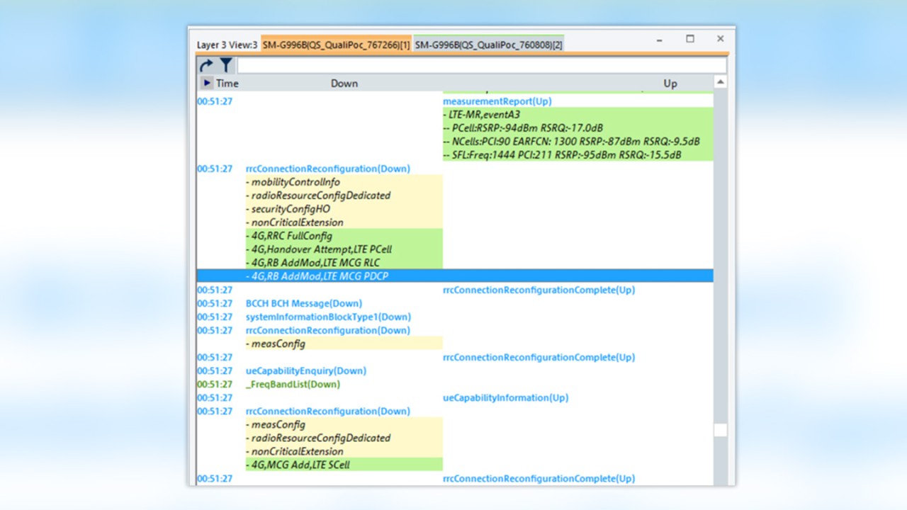
Below is our previous LTE handover in the layer 3 view with the smart RRC events seen with a green background in the source RRC message.
The signaling sequence is now easier to understand, even for non-experts.
The smart RRC events explain:
1. LTE -MR Event A3 triggered the measurement report and provides the measured cell quality results for the PCells, neighbor cell(s) and SCells (SFL).
2. LTE eNB acts upon an MR Event A3 and initiates an RRC reconfiguration while R&S®ROMES4 detects the following smart RRC events:
a) Handover attempt for LTE PCell: handover to a new primary cell on the same frequency (inter-frequency handover)
b) RB AddMod: RLC and PDCP configuration of the data radio bearer
3. The next RRC reconfiguration activates carrier aggregation, as indicated by the MCG add LTE SCell event.
Analysis samples
A vast set of parameters are available to control mobility functions, such as handovers and dual connectivity. High mobility performance levels in mobile networks require that parameters be fine-tuned to geographical conditions, frequency bands and even cell-specific conditions. So, a mobile network will need a lot of tuning throughout its lifecycle.
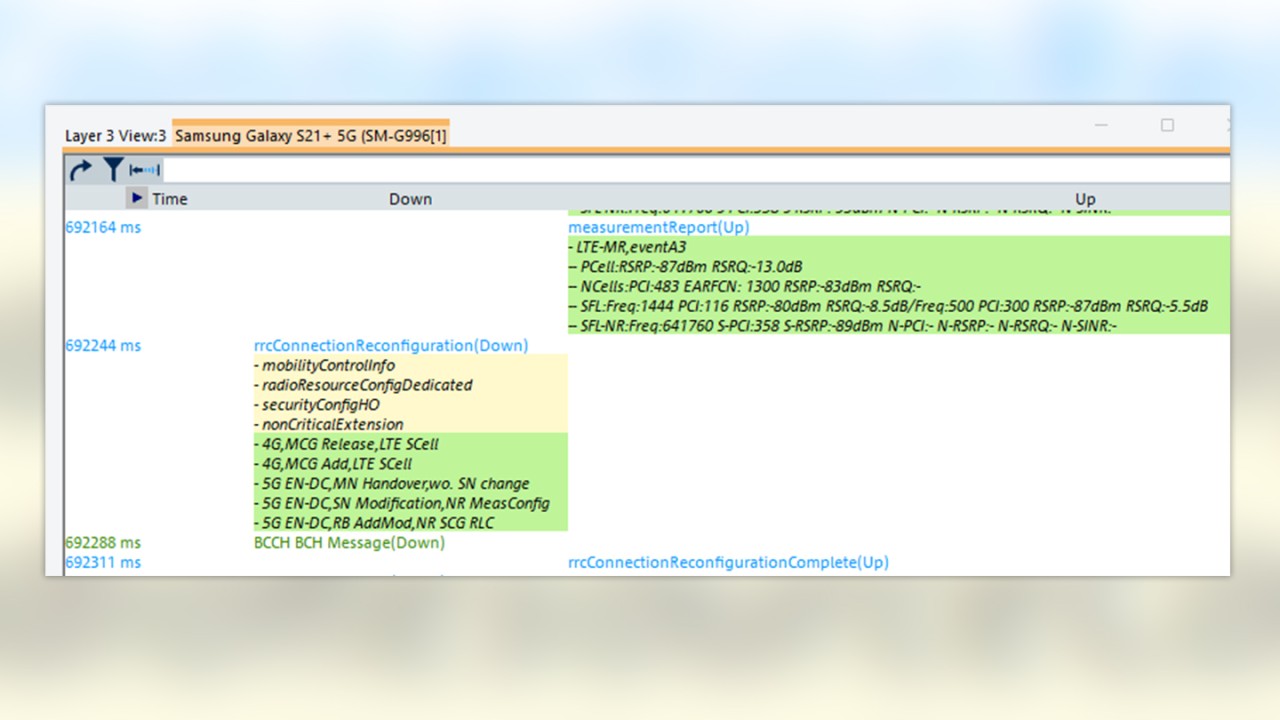
Measurement reporting configurations can be event driven or periodic. An Event A3 is the common intra-frequency handover trigger, indicating that a neighbor cell has offset of x dB relative to the serving cell. the next example depicted below shows an LTE-MR Event A3 triggering a measurement report for the PCI 483 neighbor cell with an RSRP of -83 dBm and a serving cell with -87 dBm, meaning the neighbor cell is 4 dB better. NodeB responds with an RRC reconfiguration message and a handover to the new cell.
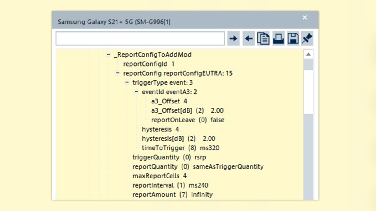
In an earlier RRC reconfiguration message you can find the Event A3 configuration to cross-check the reporting conditions and make sure that the offset [dB] plus hysteresis [dB] are in fact 4 dB.
LTE was the first cellular technology with a self-organizing network (SON) function: the automatic neighbor relation (ANR) feature. Network operators around the world welcomed this feature, since significantly reduced the effort needed to manage neighbor cell relations, which were very challenging in legacy 2G and 3G networks.
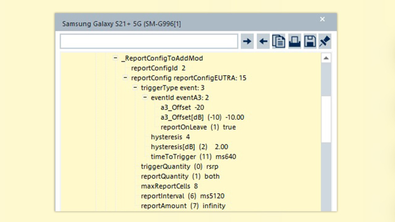
ANR is embedded in the overall LTE measurement quality procedures with individual measurement reporting configurations. ANR can instruct the UE to report neighbor cells with a negative offset before they are detected as handover candidates by other Event A3 configurations.
In the example below the Event A3 parameters offset plus hysteresis are instead -12 dB.
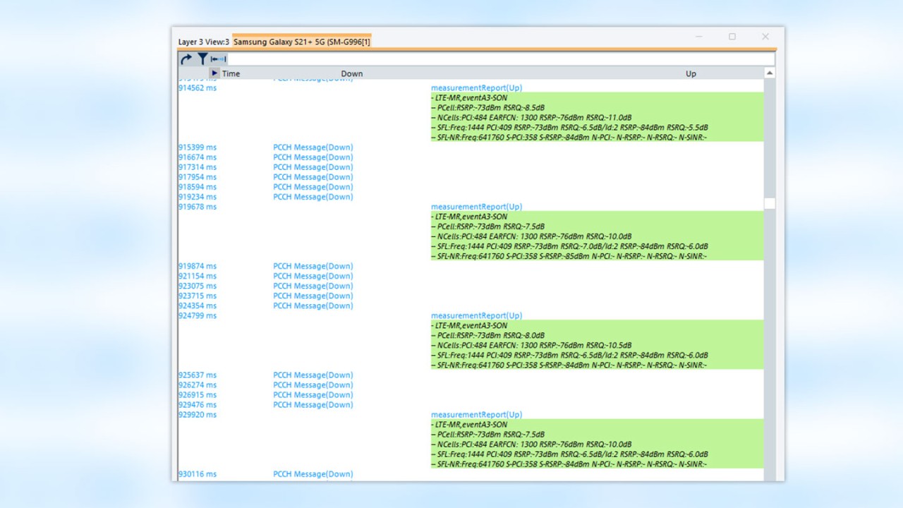
R&S®ROMES4 makes it easy to distinguish between Event A3 measurement reports used to trigger handovers and those used for SON functions. Multiple instances of Event A3 SON are reported but the negative offset prevents a handover decision in the NodeB.
Missing neighbor problems are the most common cause of dropped calls and poor connection quality. When a UE sends measurement reports to the primary cell indicating a better neighbor cell and no response comes from the NodeB (i.e. no RRC reconfiguration), the UE will probably will drop the connection due to poor signal quality and start the RRC re-establishment process.
Relationships with neighbor cells may not be defined in the primary cell due to a suboptimal ANR function. Other reasons may include heavy traffic loads in a neighboring cell.
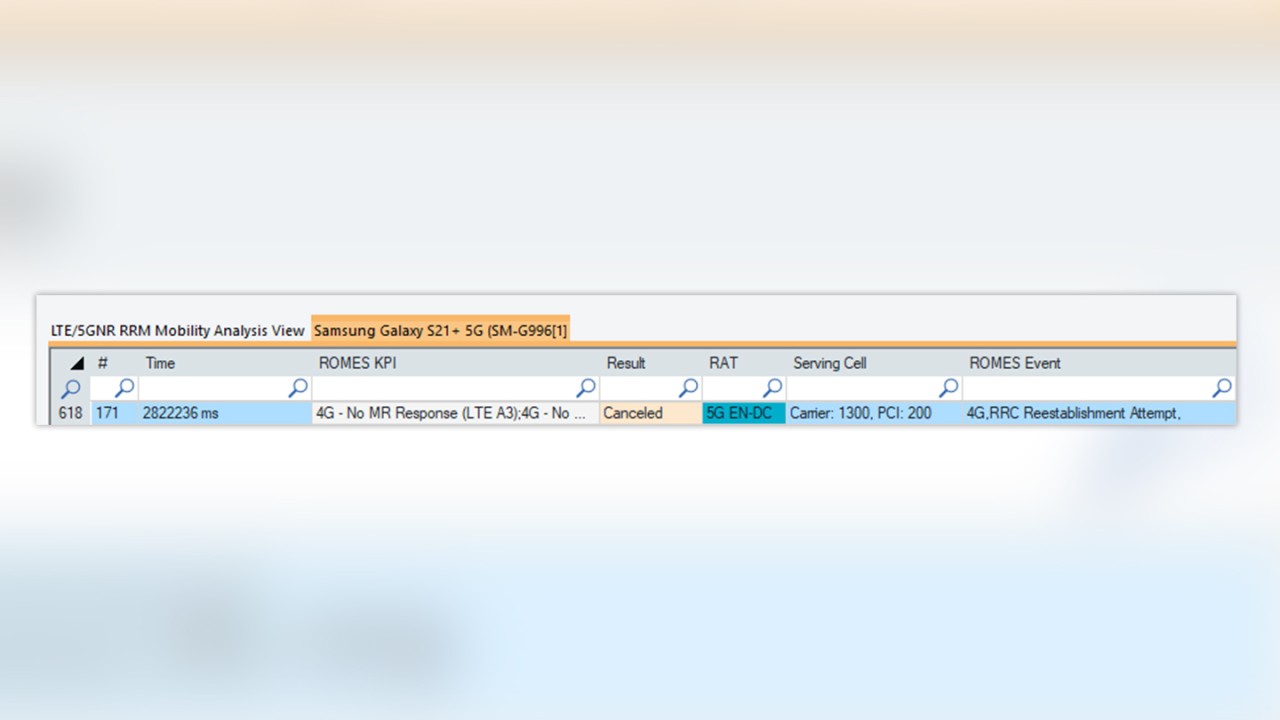
R&S®ROMES4 has the 'No MR response' KPI to make it easier to detect situations with no response from the UE measurement and quickly identify such problems.
The KPI helps find problems and decoded RRC MR events help understand them.
Event A3 defined for SON (negative offset) is not taken into consideration for the 'No MR response' KPI, since it does not trigger a NodeB response.


